Make, Tcl, and Bender Build System.
Updated 1 May 2026: Corrected stale links.
The Hello World build in the previous post is a GUI-driven Vivado project. I would like to upgrade to a hierarchical, command-line-driven build system. In a command-line-driven build system, it’ll be easier to automate tasks and it’ll be easier to integrate tools that are not part of Vivado, such as Cocotb and Verilator.
Terminology and References
- CocoTB: A Python-based framework for digital logic verification. See https://www.cocotb.org/.
- Constraints File: A constraints file specifies the mapping of the top-level HDL module’s input and output ports to physical pins of the FPGA. It also defines the clocks used by the given design. See https://digilent.com/reference/programmable-logic/guides/vivado-xdc-file.
- EDA tool: A software tool to design electronic circuits, e.g. Vivado.
- IP-XACT: An XML format that defines and describes individual, re-usable electronic circuit designs to facilitate their use in creating integrated circuits.
- IP Package: A Vivado file encapsulating an IP component using the IP-XACT file format.
- Makefile: A file used by the Make utility, defining a set of tasks to be executed, and defining dependencies between tasks. Makefiles are commonly used to create build systems.
- Memory File: A file containing the initial contents of a Block RAM instance used in an FPGA design.
- OOC: Vivado’s OOC mode or OOC flow lets you synthesize, implement, and analyze design modules in a hierarchical design.
- Tcl: The defacto standard embedded command language for EDA applications.
- Verilator: A tool that converts Verilog to a cycle-accurate behavioral model in C++ or SystemC. The performance of the generated behavioral model is generally much higher than that of a traditional event-driven simulator. See https://www.veripool.org/verilator/.
Vivado IP Packages
Vivado has an embedded, Tcl-based command-line interface. For every GUI action, there’s an equivalent Tcl command or set of commands. My initial approach to creating a build system was to use a combination of Makefiles and Tcl scripts to get Vivado to generate a so-called IP Package for each component. These IP Packages then constitute the building blocks of our system: IP Packages can be aggregated into bigger IP Packages. A top-level project build aggregates IP Packages into an SoC.
This approach has some advantages:
- It’s hierarchical: A big SoC build is (recursively) broken down into manageable components.
- It doesn’t introduce any new tool dependencies other than GNU Make.
Along the way, I learned that Vivado IP Packages also have some disadvantages:
- SystemVerilog is not supported at the top-level, i.e. I have to create Verilog wrappers around SystemVerilog-based components. That’s not the end of the world, but it does feel like a step backward.
- Vivado IP Packages come in a standard format called IP-XACT. If I want to create a flat list of files that make up a project, e.g. to feed to Verilator or Cocotb, I need a tool to extract information from IP-XACT files. I was able to find one tool, called Kactus 2, but that appears to be a full-fledged graphical EDA application, rather than a command-line utility. As long as I can’t easily interface to IP-XACT files, I’m locked into Vivado and won’t be able to use third-party tools like Verilator or Cocotb.
That last item is a deal-breaker for me. I start looking for other options.
FuseSoc
https://fusesoc.readthedocs.io/en/stable/
FuseSoc is a package manager and build system for HDL code. HDL builds can be retargeted from one EDA tool to another with the flip of a switch, so to speak. The tool is already in use by projects such as Ibex, and it looks very promising, so I decide to give it a shot…
Creating a so-called FuseSoc core file, a manifest defining the component, is easy enough. Once you have such a core file, you can instruct the tool to generate, for instance, a Vivado or a Verilator build for it. The problem is, I have no idea how it works. When I kick off a Fusesoc Verilator build, I get a nice OK message at the end, but I have no idea what that means, or what happened along the way. It’s also not clear to me how to customize the flow to accommodate use cases that are not already built into the tool. I see there’s a hook mechanism, but it’s not documented. Overall, I’m not in control of this build system. I just have to hope that FuseSoc does the right thing.
Advantages:
- Handles dependency management as well as EDA tool interfacing (through Edalize).
- Supports many different EDA tools.
- Very easy to retarget a build from one EDA tools flow (e.g. Vivado synthesis) to another (e.g. a Verilator build)
Disadvantages:
- Not sufficiently documented.
- Not clear how to customize for use cases that are not built-in. E.g. How to integrate Cocotb?
- Behind-the-scenes magic: The user of the tool is not in the driver’s seat.
- Additional tool dependencies and associated learning curve: FuseSoc itself, Python, etc.
FuseSoc has a lot of potential. It works for a lot of people (e.g. Ibex), but in its current form, it’s not a good match for me.
Bender
https://github.com/pulp-platform/bender
Where FuseSoc aims to control the entire flow itself, Bender aims to do just one thing: Dependency Management for hardware design projects. Bender itself is not a build system. It’s a tool that feeds the build system.
Central to Bender is the package manifest bender.yml. In the manifest, you specify the HDL sources that make up the package, dependencies, include paths, targets (e.g. synth, sim), and associated defines. A package directory is a directory containing a bender.yml file. When you run bender in that directory, you can ask it to generate a flat list of all the sources from the current package, and the packages it depends on. Optionally, it can generate that list, plus any defines associated with a given target, as a Tcl script. This makes integration with Vivado very easy.
You can of course do all those things yourself using Makefiles and shell scripting, but it’s very tedious, and you know you’re reinventing the wheel for the umpteenth time. Bender absorbs a lot of the hassle of creating a build system, but you are still in the driver’s seat.
Advantages:
- Dependency management is elegantly taken care of.
- A tool that feeds the tools. Easy to integrate into a custom build flow.
- Minimal learning curve. The info in the README is all you need.
- Minimal tool dependency: bender is a single binary executable.
Disadvantages:
- Doesn’t do much in way of EDA tool interfacing. That’s left up to the build system creator.
That’s good enough for me. I’m going for a Makefile-Tcl-Bender combo build system.
The Build System
Project View of the Build System
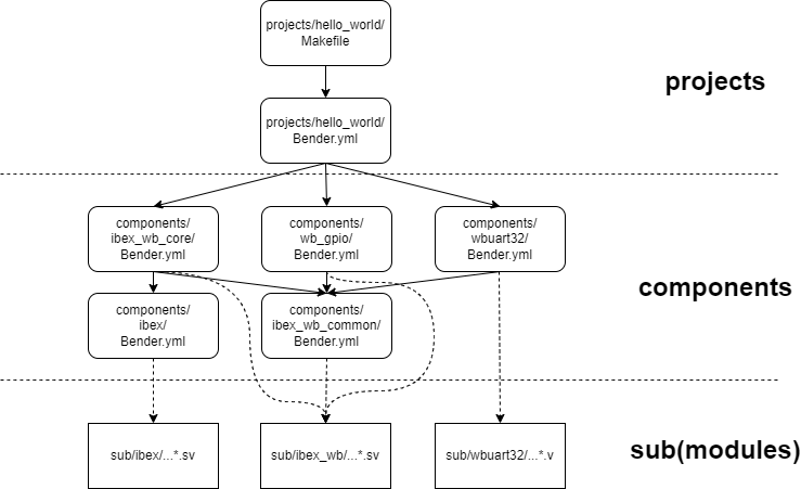
The build system has three layers:
- The Project Layer (top): Hello World is an example project. A project is the top layer of the build system. The bender.yml manifest contains the top-level files of an SoC build, the project’s .xdc constraints file, memory files used by the SoC, and a list of components the project depends on.
- The Component Layer (middle): Components are the middle layer of the build system. They are the building blocks of an SoC. A component’s sources, defines, and dependencies are defined in a bender.yml manifest. A component gets its HDL sources from its rtl/ subdirectory and/or from sub/, the submodule layer. I’m considering each Wishbone Bus Master or Slave a component.
- The Submodule Layer (bottom): Submodules are the bottom layer of the build system. They are the Git Submodules that BoxLambda is referencing, as discussed previously.
I reshuffled the repository’s directory structure a bit to reflect the three layers:
boxlambda
├── build_sys
├── projects
│   └── hello_world
├── components
│   ├── ibex
│   ├── ibex_wb_common
│   ├── ibex_wb_core
│   ├── wb_gpio
│   └── wbuart32
└── sub
    ├── ibex
    ├── ibex_wb
    └── wbuart32
The Project Build Makefile
A project directory, such as projects/hello_world/, contains a top-level Makefile, with the following build targets:
- dryrun: Generate a Vivado project, but don’t build it.
- synth: Generate a Vivado project and synthesize it.
- impl: Generate a Vidado project, synthesize it, and implement it.
- run: Download the generated bitstream file to the target. Note: The script this build target executes is configured for my WSL-based setup. It may need customization for other setups.
- clean: Remove all generated files in the current directory and subdirectories.
What happens when you run make synth
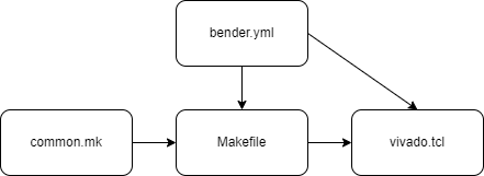
When you run make synth, the following happens:
- Make runs a bender script command.
- The bender script command processes the current directory’s package manifest (bender.yml), as well as the package manifests of any dependent components.
- The bender script command emits a list of all the HDL sources that make up the project.
- Make feeds this file list, along with a .xdc constraints file and any .mem memory files, into a vivado.tcl script.
- The vivado.tcl script generates a Vivado project file containing all the HDL sources, constraints, and memory files.
- The vivado.tcl script kicks off synthesis and generates timing and utilization reports when synthesis is complete.
When you run make impl, the same thing happens, but after completing synthesis, the vivado.tcl script proceeds to kick off implementation and bitstream generation.
The Build System Files - arrows indicate information flow.
The relevant files are linked below. To avoid repeating identical rules and variables across Makefiles, a build_sys/common.mk include file is created which contains all reusable Makefile logic.
- build_sys/common.mk
- projects/hello_world/Makefile
- projects/hello_world/Bender.yml
- build_sys/vivado.tcl
A Component Build
Components can also be synthesized, in Out-Of-Context (OOC) Mode. In OOC mode, the synthesizer is made aware that the top-level module’s input and output ports are not tied to chip pins, i.e. that this is just a partial build. A component Makefile works the same as a project Makefile, but with an OOC Makeflag set and propagated to Vivado.
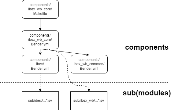
Component View of the Build System
About Memory Files
Memory files used by an FPGA build are typically generated from software. It would be annoying to have to build the hello world program, to generate a memory file, and then build the FPGA in a separate step. As a rule, a build system should start from sources, not from build artifacts created separately by other build systems.
To combine the software and FPGA build steps, the build system has a pattern rule for .mem memory files. Whenever the build system encounters such a file as a dependency, it goes to that file’s directory and runs make there, to make sure that the .mem file gets generated.
#Pattern rule for memory files: Go to the memory file's directory and run Make there.
%.mem : force
	$(MAKE) -C $(@D)
The current mechanism just assumes that the default rule in the recursive make will do the right thing. It’s a bit crude, but it’s a start.
Second Iteration complete
The second iteration is complete. We still have a working hello world proof-of-concept project, but now it’s generated from an actual command-line-driven build system.
I did make a small change to hello.c: After printing out Hello world, the program goes in a loop toggling the LEDs. This way, the program exercises the GPIO core as well as the timer core in addition to the UART core.
To build the project:
- Install the prerequisites.
- git clone https://github.com/epsilon537/boxlambda/,
- cd boxlambda
- Switch to the make_and_bender tag: git checkout make_and_bender.
- Get the submodules: git submodule update –init –recursive.
- Build the project:
- cd projects/hello_world
- make impl
- Start Vivado and download the generated bitstream to your Arty A7-35T: projects/hello_world/generated/project.runs/impl_1/ibex_soc.bit
Interesting Links
In the Beginning Was the Command Line : A famous essay by Neal Stephenson about command-line interfaces vs. GUIs, closed vs. open source, and Apple vs. Microsoft, among other things.