Post-Implementation Memory Updates.
Updated 2 April 2026: Corrected stale links.
Updated 18 July 2023: Added the RAM_DECOMP(“power”) section.
Updated 23 December 2025:
- Removed reference to ‘On WSL’ documentation.
- Fixed link to build system in documentation.
I’ve been working on the integration of a sound synthesizer core and player software for that core. I’m still relying heavily on my Verilator test bench, but increasingly, I’m hitting the limits of that environment. Evaluating a 30-second fragment of a chiptune requires 30s simulation time, which in my case translates to 75 minutes in real-time. Not impossible, but inconvenient when you have to re-test frequently, e.g. due to software changes.
On the Arty FPGA, the 30s chiptune test executes in real-time, but Vivado synthesis and implementation of the project takes 10 minutes on my system. Again, doable, but inconvenient, especially considering that in my current flow, a software change requires FPGA resynthesis and reimplementation. The generated software image is a .mem file for an internal memory. This .mem file has to be included in the Vivado project like any other input file, before synthesis.
UpdateMem and XPM Memories
If you think about it, a change in the contents of a .mem file should not require FPGA resynthesis and reimplementation. The memory contents exist somewhere in the FPGA bitstream file. There should be a way to merge new memory contents into the bitstream file, post-implementation.
This is indeed possible in Vivado. The tool that does it is called UpdateMEM. There is a catch, however. UpdateMEM works with memories implemented using Xilinx XPM macros.
When Vivado implements an XPM memory such as xpm_memory_spram, a so-called MMI file, or Memory Map Information file is generated. An MMI file describes how individual block RAMs make up a contiguous logical data space. The UpdateMem tool needs this information to determine the locations in the bitstream file to update.

Merging a .mem file into a Bitstream File.
The disadvantage of using XPM memories is that they’re Xilinx-specific. By using them, I’m tying BoxLambda more to Xilinx’s eco-system and am making it more difficult to port the project to other FPGA platforms. I’ll keep my eyes open for a vendor-agnostic solution. I think it may require switching over to an open-source toolchain entirely. F4PGA maybe? It would be an interesting side project, but for the time being I will switch over BoxLambda’s internal memory to an xpm_memory_spram instance when synthesizing for the Arty A7.
Processor Required?
UpdateMem also requires the instance path of the embedded processor associated with the memory in question. It’s not entirely clear to me why this is needed and what to plug in in case of a RISCV-based design. The UpdateMem documentation is geared toward Xilinx Microblaze processors. Luckily, UpdateMem itself provides helpful suggestions when you plug in something silly:
$ updatemem -bit ibex_soc.bit -meminfo ibex_soc.mmi -data spram.mem -proc i_dont_know -out ibex_soc.out.bit

****** updatemem v2023.1 (64-bit)
...
source /tools/Xilinx/Vivado/2023.1/scripts/updatemem/main.tcl -notrace
Command: update_mem -meminfo ibex_soc.mmi -data spram.mem -proc i_dont_know -bit ibex_soc.bit -out ibex_soc.out.bit
0 Infos, 0 Warnings, 0 Critical Warnings and 1 Errors encountered.
update_mem failed
ERROR: [Updatemem 57-85] Invalid processor specification of: i_dont_know.
The known processors are: wb_spram/xpm_memory_spram_inst/xpm_memory_base_inst
OK. Easy enough. I have to use wb_spram/xpm_memory_spram_inst/xpm_memory_base_inst as the processor instance.
Out of curiosity, I also tested with an XPM memory that’s not hooked up to any processor. I just hooked up the memory to GPIOs. Sure enough, a .MMI file got generated and I was able to update the memory’s contents in the bitstream file using UpdateMEM. UpdateMEM can be used on processorless systems and on memories that are not associated with any processor.
RAM_DECOMP(“power”)
For XPM memories up to 64KB, Updatemem works fine. However, with an XPM memory size of 256KB, Vivado switches to a different, less straightforward, memory layout and Updatemem no longer updates the bitstream correctly. To work around that issue, I instantiate the XPM memory with the RAM_DECOMP attribute set to “power”. This forces Vivado to stick to a straighforward memory layout for bigger memory sizes, so Updatemem can still update the bitstream correctly.
One drawback of this workaround is that the XPM memory RAM_DECOMP attribute has only been introduced in the V2023.1 edition of Vivado. It won’t work on earlier versions.
BoxLambda Implementation
Instantiating the XPM Memory
For Boxlambda’s internal memory I’m using the xpm_memory_spram macro, instantiated as follows:
xpm_memory_spram #(
   .ADDR_WIDTH_A(addr_width),     // DECIMAL
   .AUTO_SLEEP_TIME(0),           // DECIMAL
   .BYTE_WRITE_WIDTH_A(8),        // DECIMAL
   .ECC_MODE("no_ecc"),           // String
   .MEMORY_INIT_PARAM("0"),       // String
   .MEMORY_OPTIMIZATION("true"),  // String
   .MEMORY_PRIMITIVE("auto"),     // String
   .MEMORY_SIZE(size*8),          // DECIMAL, memory size in bits
   .RAM_DECOMP("power"),          // String, for updatemem compatibility
   .MESSAGE_CONTROL(0),           // DECIMAL
   .READ_DATA_WIDTH_A(32),        // DECIMAL
   .READ_LATENCY_A(1),            // DECIMAL
   .READ_RESET_VALUE_A("0"),      // String
   .USE_MEM_INIT(1),              // DECIMAL
   .WAKEUP_TIME("disable_sleep"), // String
   .WRITE_DATA_WIDTH_A(32),       // DECIMAL
   .WRITE_MODE_A("read_first")    // String
)
xpm_memory_spram_inst (
   .dbiterra(),             // 1-bit output: Status signal to indicate double bit error occurrence
                                    // on the data output of port A.

   .douta(ram_q),            // READ_DATA_WIDTH_A-bit output: Data output for port A read operations.
   .sbiterra(),             // 1-bit output: Status signal to indicate single bit error occurrence
                           // on the data output of port A.

   .addra(ram_addr),                   // ADDR_WIDTH_A-bit input: Address for port A write and read operations.
   .clka(wb.clk),                     // 1-bit input: Clock signal for port A.
   .dina(ram_d),                     // WRITE_DATA_WIDTH_A-bit input: Data input for port A write operations.
   .ena(ram_ce),                    // 1-bit input: Memory enable signal for port A. Must be high on clock
                                   // cycles when read or write operations are initiated. Pipelined
                                  // internally.

   .injectdbiterra(1'b0), // 1-bit input: Controls double bit error injection on input data when
                         // ECC enabled (Error injection capability is not available in
                        // "decode_only" mode).

   .injectsbiterra(1'b0), // 1-bit input: Controls single bit error injection on input data when
                         // ECC enabled (Error injection capability is not available in
                        // "decode_only" mode).

   .regcea(1'b1),                 // 1-bit input: Clock Enable for the last register stage on the output
                                 // data path.

   .rsta(wb.rst),                     // 1-bit input: Reset signal for the final port A output register stage.
                                     // Synchronously resets output port douta to the value specified by
                                    // parameter READ_RESET_VALUE_A.

   .sleep(1'b0),                   // 1-bit input: sleep signal to enable the dynamic power saving feature.
   .wea(ram_we)                        // WRITE_DATA_WIDTH_A-bit input: Write enable vector for port A input
                                      // data port dina. 1 bit wide when word-wide writes are used. In
                                     // byte-wide write configurations, each bit controls the writing one
                                    // byte of dina to address addra. For example, to synchronously write
                                   // only bits [15-8] of dina when WRITE_DATA_WIDTH_A is 32, wea would be
                                  // 4'b0010.
);
Build Rules
I organized the gateware build rules as follows:
- make <project>_synth: Synthesize the given gateware project. The output of synthesis is a .dcp checkpoint file.
- make <project>_bit: Implement the given gateware project and generate its bitstream. This is a file with extension .bit. Note that only the gateware is built, not the SW project running on top of this gateware. The internal memory reserved for the software program will be left empty. This target depends on the <project>_synth target.
- make <project>_bit_sw: The project software image is merged into the FPGA bitstream file. The result is a file with extension .sw.bit. The <project>_bit_sw target depends on the <project>_bit target above and on the software target associated with the gateware project.
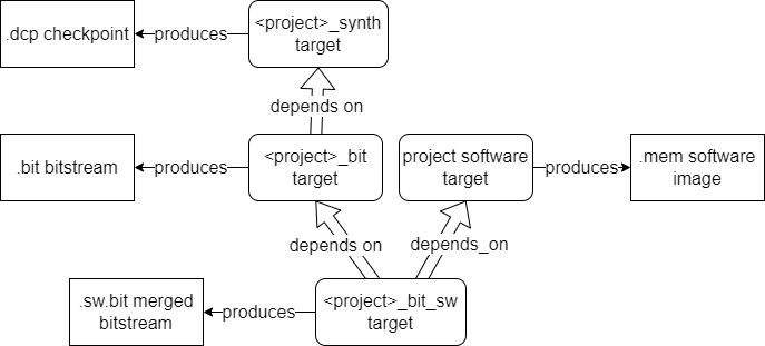
Gateware Build Targets.
For a full description of BoxLambda’s build system, see https://boxlambda.readthedocs.io/en/jun_18_23/build-system/.
Other BoxLambda Changes
- I added limited C++ support to the build system. This boiled down to two things:
-
Adding a CXX compiler and flags in the toolchain.cmake file. The CXX flags reduce the C++ environment such that there’s no C++ run-time environment required, at the expense of thread-safe statics and exception handling:
set(CMAKE_CXX_COMPILER riscv32-unknown-elf-gcc) set(CMAKE_CXX_FLAGS_INIT "-msave-restore -fshort-enums -march=rv32imc -mabi=ilp32 -fno-threadsafe-statics -fno-exceptions") -
Surrounding C-based APIs (I have a mixed bag of C and C++ code) with extern “C” {} brackets for compatibility with C++ code.
  #ifdef __cplusplus
  extern "C" {
  #endif
  ...
  #ifdef __cplusplus
  }
  #endif
-
- I created two linker script variants:
- boxlambda/sw/components/bootstrap/link_internal_mem_64K.ld: This is the linker script for an internal memory size of 64KB. This script results in a software image that can run both on the Arty-A7-35T and the Arty-A7-100T (FPGA and simulation).
- boxlambda/sw/components/bootstrap/link_internal_mem_256K.ld: This is the linker script for an internal memory size of 256KB. This script results in a software image that only runs on the Arty-A7-100T (FPGA and simulation).
- I created two simulation build tree variants:
- sim-a7-35 for Verilator simulation of Arty-A7-35T builds
- sim-a7-100 for Verilator simulation of Arty-A7-100T builds.
Try It Out
Setup
- Install the Prerequisites.
- Get the BoxLambda repository:
git clone https://github.com/epsilon537/boxlambda/ cd boxlambda - Switch to the updatemem tag:
git checkout updatemem - Set up the repository. This initializes the git submodules used and creates the default build trees:
./boxlambda_setup.sh
Hello World on Arty A7
- Build and time the hello_world project in an Arty A7 build tree (arty-a7-35 or arty-a7-100):
cd build/arty-a7-35/gw/projects/hello_world time make hello_world_bit_sw - Connect a terminal program such as Putty or Teraterm to Arty’s USB serial port. Settings: 115200 8N1.
- Download the generated bitstream file to the Arty A7:
make hello_world_load -
Verify the test program’s output in the terminal. You should see something like this:
Hello, World! This is not a simulation. - Modify the hello world source code: boxlambda/sub/ibex_wb/soc/fpga/arty-a7/sw/examples/hello/hello.c. E.g. change the string
"Hello, World!\n"to"Hola, Mundo!\n". - Rebuild and time the hello_world project:
time make hello_world_bit_sw - Note that the build time is just a few seconds now, whereas it was a few minutes the first time around.
- Download the generated bitstream file to the Arty A7 to make sure that the bitstream includes the modified hello message:
make hello_world_load
Conclusion
With the UpdateMEM-based build flow, software changes are picked up and merged into the FPGA bitsteam file in a matter of seconds. This makes the lather-rinse-repeat loop of testing software on FPGA significantly shorter. This approach only works for small programs that fit in internal memory, however. At some point, I will have to load larger software programs into DDR memory. In such a scenario, I will have to resort to a JTAG and/or BIOS-based boot sequence.