Chiptunes! A Dual YM2149 PSG Audio core for BoxLambda.
Updated 2 April 2026: Corrected stale links.
Updated 23 December 2025:
- Corrected link to Bender in documentation.
- Removed reference to ‘On WSL’ documentation.
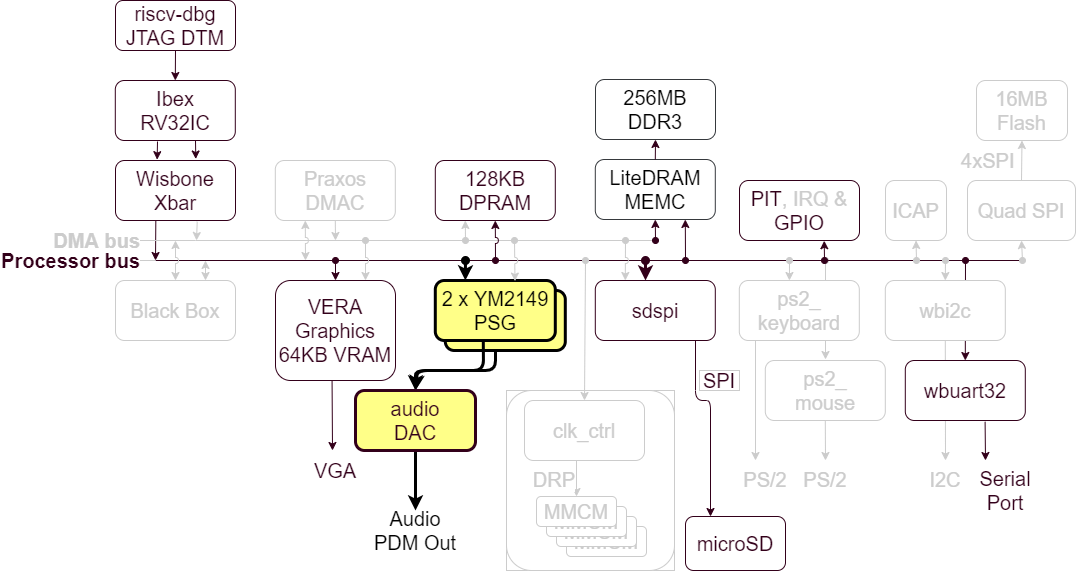
A dual YM2149 PSG core in the BoxLambda Architecture.
An FPGA-based, retro-style computer needs a retro synthesizer core. I added a Dual YM2149 PSG core to BoxLambda. Each core provides three PSG channels, so one core can play a 3-channel audio track and the other core can play up to three overlapping sound effects. Pew-Pew!
To get the synthesized audio off the chip, I’m using a 1-bit second-order delta-sigma DAC hooked up to Digilent’s PMOD Amp2 audio amplifier.
Recap
This is a summary of the current state of affairs for BoxLambda. We have:
- An Ibex RISC-V core, Wishbone shared bus, timer, two GPIO ports, UART core, and internal memory.
- DDR3 external memory access through the Litex Memory Controller.
- OpenOCD-based Debug Access, both on FPGA and Verilator.
- VERA-based VGA graphics: 2 layers tile or bitmap mode, 2 banks of 64 sprites, 128KB Video RAM, 256 color palette.
- SD Card Controller and FatFs File System.
- Test builds running on Arty-A7-35T, Arty-A7-100T, and Verilator.
- A Picolibc-based standard C environment for software running on the Ibex RISC-V core.
- A Linux CMake and Bender-based Software and Gateware build system with support for automated testing and post-implementation memory updates.
Programmable Sound Generators (PSG)
A Programmable Sound Generator is a chip that generates sound by combining multiple basic waveforms (channels). Typical waveforms used are square waves, triangular waves, and noise. The shape, frequency, and volume of the different waveforms are configured by the CPU through a register interface.
PSGs chips usually also include one or more envelope generators that control the variation of the sound’s volume over time (ramp up, hold, ramp down, etc.). Different envelope shapes and associated parameters can be configured through the register interface.
The YM2149
The YM2149 is a little PSG chip used in 80s arcade games, consoles, and home computer systems such as MSX and the Atari ST. The chip has a 3-channel square wave generator, a noise generator, and an envelope generator. Here’s the datasheet: http://www.ym2149.com/ym2149.pdf
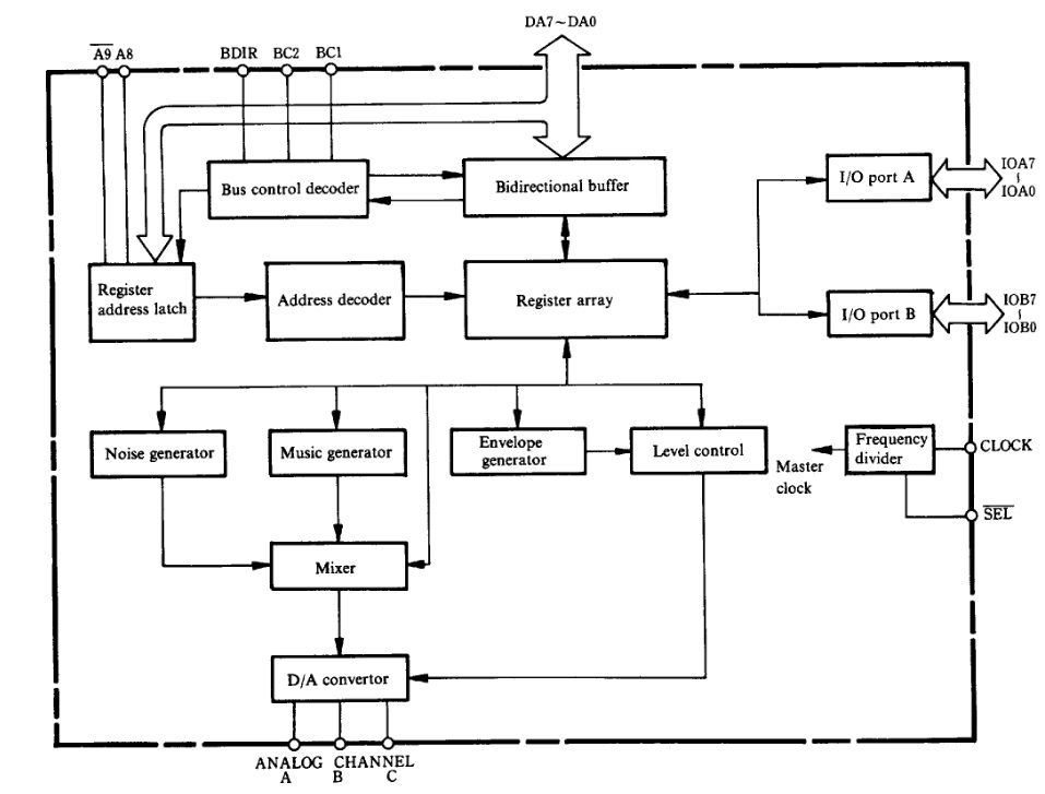
YM2149 Block Diagram as shown in the datasheet.
A Dual YM2149 PSG Audio core: YM2149_PSG_System
When you’re searching online for a YM2149 implementation, you’ll quickly come across Jotego’s JT49 core:
https://github.com/jotego/jt49
My initial plan was to instantiate this core twice and add the PCM output signals together. However, looking a little further, I found a project from Nockieboy that already did that and added a nice audio mixer with volume, treble, and bass controls:
https://github.com/nockieboy/YM2149_PSG_system
The project even supports I2S output, but currently, I just have a simple audio amplifier PMOD, so I wouldn’t be using I2S (I added it to the wishlist).
For the most part, I was able to use the YM2149_PSG_system code as-is. I just had to make a few small tweaks to integrate the core into BoxLambda:
- I added a Wishbone front end.
- I made I2S support optional, controlled by a USE_I2S define.
- Rather than have the top-level YM2149_PSG_system module include the Verilog files of the submodules it depends on, I added all required modules separately to the BoxLambda project in a Bender.yml manifest (see https://boxlambda.readthedocs.io/en/aug_19_23/build_sys_gw_build_struct/#bender). BoxLambda’s build system dependency checking doesn’t work well will Verilog modules including other Verilog modules.
- I made a few code tweaks to pacify Vivado’s synthesizer.
I forked the YM2149_PSG_system repo to track my changes:
https://github.com/epsilon537/YM2149_PSG_system
YM2149 PSG System Overview
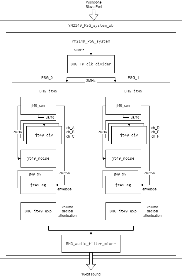
YM2149 PSG System Block Diagram.
The design of the YM2149_PSG_system core is easy to follow:
- YM2149_PSG_system_wb is a Wishbone wrapper around the YM2149_PSG_system core.
- BHG_jt49 represents one YM2149 device. YM2149_PSG_system instantiates two such modules and feeds their output to the BHG_audio_filter_mixer.
- BHG_audio_filter_mixer implements mixing logic, individual channel volume controls, master volume control, treble, and bass controls.
- Looking into the BHG_jt49 module:
- jt49_div is a configurable square wave generator module. It is instantiated three times, so we have three channels.
- jt49_noise is a noise generator module (e.g. for percussion effects).
- jt49_eg with the assistance of a fourth jt49_div instance is the sound envelope generator.
- jt49_cent generates clock enables at the appropriate rate for the above modules.
- BHG_jt49_exp provides decibel-based volume attenuation through a look-up table.
The core can be configured to produce stereo I2S output, but for BoxLambda we’ll set it up to produce 16-bit PCM mono audio.
The input clock frequency and PSG clock frequency (clock enable) are core module parameters. In BoxLambda, the core will be instantiated with a clock frequency of 50MHz (BoxLambda’s system clock) and a PSG clock frequency of 2MHz. I set the PSG clock frequency to 2MHz to match the Atari ST.
A Second Order Delta-Sigma DAC
The YM2149_PSG_System core produces 16-bit PCM audio. The audio amplifier PMOD expects the audio signal on a single pin, however. To bring 16-bit PCM audio to a single digital pin, we need a one-bit Digital-to-Analog converter. If you’ve never heard of one-bit DACs before, it probably sounds terrible, but it works quite well. The idea is to generate, at a rate much higher than the input sample rate, a stream of pulses such that a moving average going over the pulse stream produces a signal that tracks the input 16-bit PCM signal.

1-bit delta-sigma modulation (blue) of a sine wave (red) - taken from Wikipedia.
In analog electronics, a moving average is created by attaching a simple low-pass RC filter to the one-bit-DAC pin. In our case, we don’t even have to do that, because the audio amplifier PMOD provides the low-pass filter.
There exist several ways to implement a one-bit DAC, with different pros and cons. One commonly used technique is called Delta-Sigma Conversion. It’s explained very well in the following article from Uwe Beis:
https://www.beis.de/Elektronik/DeltaSigma/DeltaSigma.html
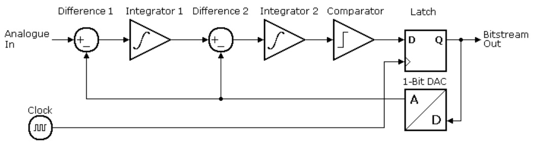
Second Order Delta Sigma Modulator Block Diagram from https://www.beis.de/Elektronik/DeltaSigma/DeltaSigma.html.
I’ll be using a Second Order Delta-Sigma DAC. An advantage of a second-order delta-sigma DAC is that it (more than its first-order counterpart) pushes the noise introduced by the Digital-to-Analog conversion out of the way, to higher frequency ranges where gets filtered out by the low-pass filter.
The Uwe Beis article above describes the idea well enough. However, I was unable to find a reference implementation that made sense to me. I ended up writing my own, borrowing ideas from the following implementations I found online:
- https://forum.digilent.com/topic/20332-second-order-sigma-delta-dacs-implemented-in-a-fpga/?do=findComment&comment=65787
- https://github.com/briansune/Delta-Sigma-DAC-Verilog?_ga=2.154876920.117504330.1692006910-1995131070.1681993594
Here is my Verilog code:
It wasn’t obvious to me how to size the two accumulators used in the implementation so that they don’t overflow and create conversion errors. I ended up adding logic that checks for overflows and experimented with different audio samples. The outcome was that for a 16-bit input signal, the stage-1 accumulator needs to be 20 bits in size and the stage-2 accumulator needs to be 22 bits in size.
The Audio DAC Test Project
I created a test project to test the one-bit DAC. The RTL consists of a sine wave generator connected to an instance of the one-bit DAC. The top-level module output ports include:
- The 16-bit PCM sine wave signal (Verilator build only)
- The one-bit DAC output signal
- The stage-1 accumulator overflow detect signal from the one-bit DAC (Verilator build only).
- The stage-2 accumulator overflow detect signal from the one-bit DAC (Verilator build only).
Here’s the top-level Verilog:
The Verilator testbench (sim_main.cpp) samples at 12.5MHz the 16-bit PCM signal and the one-bit DAC signal. It writes out the PCM samples as a Python array to pcm_out.py and the DAC samples as a Python array to dac_out.py. The testbench will also flag an error if any accumulator overflows are reported.
The Verilator testbench executes for 0.5s simulated time. Then, a python module (dac_test.py) imports the generated pcm_out.py and dac_out.py and performs the following operations:
- The PCM samples and DAC samples are converted to numpy arrays and normalized.
- Both signals are sent through a low-pass filter.
- An FFT is taken of the filtered signals, so we have a frequency domain view and a time domain view of both signals.
- The time domain and the frequency domain versions of the two signals are plotted against each other for visual inspection.
- The filtered DAC and PCM signals are correlated against each other. This is done both in the time domain and the frequency domain. If the correlation match is higher than 99%, the test is declared successful.
The test project code is located here:
https://github.com/epsilon537/boxlambda/tree/dual_ym2149_audio/gw/projects/audio_dac_test
See the Try It Out section below for instructions to build and run the test yourself.
The YM2149 DAC Test Project - a Chord of Six Pitches.
This test project is a BoxLambda SoC with the YM2149_PSG_system core and the one-bit DAC integrated. Through software, the YM2149_PSG_system core is configured to produce six tones at six different pitches. Similar to the previous test, the Verilator testbench code checks for accumulator overflows and saves the generated audio samples to pcm_out.py and dac_out.py for further analysis in Python.
The Python script (ym2149_test.py) imports the generated dac_out.py and performs the following operations:
- The DAC samples are converted to a numpy array and normalized.
- The normalized signal is sent through a low-pass filter.
- The frequency spectrum of the filtered signal is computed.
- The spectrum’s frequency bins up to 1000Hz are analyzed and plotted.
- Six peak frequencies are identified and matched against the 6 expected pitches. If the deviation is small, the test is declared successful.
The test project code is located here:
https://github.com/epsilon537/boxlambda/tree/dual_ym2149_audio/gw/projects/ym2149_dac_test
See the Try It Out section below for instructions to build and run the test yourself.
YM Music files and ST-Sound
With the above two test projects, I confirmed that the audio DAC is working and the audio core can produce sound. I wanted to go a step further and confirm that the BoxLamdba SoC can carry a chiptune.
It looked around for a music file format that supports the YM2149. Atari ST owners may mention SNDH, but SNDH, like many other chiptune formats of that time, contains a combination of data and machine code native to the Atari ST. I needed a music file format that’s just a data format, no code.
I found the YM file format by Arnaud Carré, a.k.a. Leonard/Oxygene:
http://leonard.oxg.free.fr/ymformat.html
In addition to defining the file format, Arnaud Carré also provides ST-Sound, a library to play YM files:
https://github.com/arnaud-carre/StSound
The ST-Sound code base is written for Windows, but it was easy to add a Linux port using PortAudio. I added the Linux port to my fork of the StSound repo:
https://github.com/epsilon537/StSound
It’s convenient to have a Linux port available to cross-check against, but what I needed, of course, was a BoxLambda port of the StSound library, using the YM2149 audio core. I created the port as a BoxLambda software component:
https://github.com/epsilon537/boxlambda/tree/dual_ym2149_audio/sw/components/stsound
As you can see in the CMakeLists.txt, the port references some of the original ST-Sound library files unmodified in the stsound git submodule. The ST-Sound library files that required significant modification I copied locally to the boxlambda/sw/component/stsound/ directory.
The port is not complete. I did the bare minimum needed to be able to play back a simple YM-type 2 song. To play the more advanced subtypes, I need to add digidrums and syncbuzzer sound effects. I made a note of it.
The ST-Sound Test Project
The ST-Sound test project uses the same test SoC build as the YM2149 DAC test project above, but the software is different. The software build uses the BoxLambda stsound and fatfs libraries to load and play a YM file from an attached SD card. The Arty’s switches and buttons can be used to control master volume, treble, and bass.
Audio Fingerprinting
The Verilator test bench of the ST-Sound test project records about 5s worth of generated samples and saves them off to pcm_out.py, similar to the previous two test builds. This brings up an interesting question, however: How do we analyze this data? I.e. how do we create an automated test that checks if the given PCM sample sequence actually sounds like the first 5s of the song we want to play back? A bit-for-bit check against a reference waveform would be too brittle. A slight delay, change in volume, treble, or bass would be sufficient to break the test. We need a test that checks if a given audio fragment sounds like another given audio fragment without requiring it to be 100% identical.
One technique that can be used for this purpose is called Audio Fingerprinting. The software package that implements it is called Chromaprint. It’s a very interesting technique. Here is a nice article describing how it works:
https://oxygene.sk/2011/01/how-does-chromaprint-work/
For my test case, I’m borrowing correlation.py, a Python script that wraps around Chromaprint’s fpcalc module:
https://github.com/kdave/audio-compare
The following article describes how the Python script works:
https://shivama205.medium.com/audio-signals-comparison-23e431ed2207
The script returns a correlation score. If we have an 80% match or more, the test passes.
The Verilator test bench is located here:
The test scripts and related files are here:
https://github.com/epsilon537/boxlambda/tree/dual_ym2149_audio/gw/projects/stsound_test/test
Relevant Files and Directories
- gw/components/audio_dac/rtl/one_bit_dac.sv: The Delta-Sigma audio DAC.
- sub/ym2149_psg_system: The dual YM2149 PSG system core.
- gw/projects/audio_dac_test: The Audio DAC test project.
- gw/projects/ym2149_dac_test: The YM2149 DAC Test project.
- sub/StSound: The ST-Sound Library repo.
- sw/components/stsound: The BoxLambda port of the ST-Sound Library.
- gw/projects/stsound_test: The ST-Sound Test project.
- sw/components/ym2149_sys_hal/ym2149_sys_regs.h: YM2419 PSG system register interface.
Try It Out
Setup
- Install the Software Prerequisites.
- Get the BoxLambda repository:
git clone https://github.com/epsilon537/boxlambda/ cd boxlambda - Switch to the dual_ym2149_audio tag:
git checkout dual_ym2149_audio - Set up the repository. This initializes the git submodules used and creates the default build trees:
./boxlambda_setup.sh
Audio DAC Test on Verilator
- Build the audio_dac_test project:
cd build/sim-a7-100/gw/projects/audio_dac_test make audio_dac_test_sim - Execute the generated Verilator model:
./Vmodel DAC Output File: dac_out.py PCM Output File: pcm_out.py - The Verilator model should have generated Python files dac_out.py and pcm_out.py:
ls *.py dac_out.py pcm_out.py - Execute the Audio DAC Test Python script. Pass in the -p option to see the plots. You should see a frequency domain plot, a time domain plot, and the correlation match between the PCM and the DAC signals:
  PYTHONPATH="." ../../../../../gw/projects/audio_dac_test/test/dac_test.py -p
  Time Domain Correlation: 1.000000
  Frequency Domain Correlation: 1.000000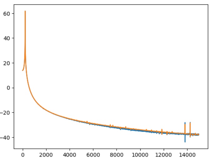
Audio DAC Test Frequency Magnitude Plot.
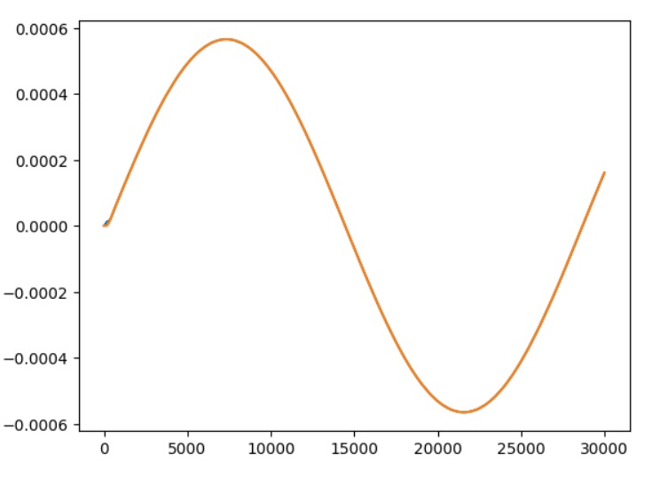
Audio DAC Test Time Domain Plot.
The plots show both the filtered PCM and DAC output signals, but because they overlap almost perfectly, you only see one waveform.
Audio DAC Test on Arty A7
- Hook up Digilent’s PMOD Amp2 to the upper row of the Arty A7 PMOD port JA.
- Build the audio_dac_test project in an Arty A7 build tree (arty-a7-35 or arty-a7-100):
cd build/arty-a7-100/gw/projects/audio_dac_test make audio_dac_test_bit - Download the generated bitstream file to the Arty A7:
make audio_dac_test_load - You should hear a 440Hz tone. You can check the pitch with a pitch detector app.
YM2149 DAC Test on Verilator
- Build the ym2149_dac_test project:
cd build/sim-a7-100/gw/projects/ym2149_dac_test make ym2149_dac_test_sim_sw - Execute the generated Verilator model. You should see the following output:
./Vmodel DAC Output File: dac_out.py PCM Output File: pcm_out.py XXXXXXXXXXXXXXXXXXXXXXXXXXXXXXXXXXXXXXXXXXXXXXXXXX XXX BHG_FP_clk_divider.v settings/results. XXX XXX https://github.com/BrianHGinc XXX XXXXXXXXXXXXXXXXXXXXXXXXXXXXXXXXXXXXXXXXXXXXXXXXXXXXXXXXXXXXXXXXXXXXXXXXXXXXXXXXXXXXXXXXXXXXXX XXX USE_FLOATING_DIVIDE = 1 XXX Set INPUT_CLK_HZ = 50000000 Hz. XXX Set OUTPUT_CLK_HZ = 2000000 Hz. XXX --------------------------------------------- (Floats only accurate to 2 decimal places) XXX True output freq = 2000000.000000 Hz. XXX Frequency error = 0.000000 ppm. XXX Periodic jitter = +/- 0.000000 ns. XXX --------------------------------------------- XXX Integer Divider = 25. XXX Divider Fraction = 0/65536. OutHz = InHz/(ID+(DF/65536)) XXX ~Divider to 6dp. = 25.000000. XXXXXXXXXXXXXXXXXXXXXXXXXXXXXXXXXXXXXXXXXXXXXXXXXXXXXXXXXXXXXXXXXXXXXXXXXXXXXXXXXXXXXXXXXXXXXX XXXXXXXXXXXXXXXXXXXXXXXXXXXXXXXXXXXXXXXXXXXXXXXXXXXXXXXXXXXXXXXXX XXX BrianHG's BHG_jt49_exp.v is using 10 bit DAC LUT table. XXX XXX https://github.com/BrianHGinc XXX XXXXXXXXXXXXXXXXXXXXXXXXXXXXXXXXXXXXXXXXXXXXXXXXXXXXXXXXXXXXXXXXX XXX dlut[0:31] = '{ 0, 1, 2, 3, 5, 6, 8, 11, XXX XXX 14, 17, 21, 26, 32, 39, 48, 58, XXX XXX 70, 84, 101, 121, 145, 174, 208, 248, XXX XXX 297, 354, 423, 505, 603, 719, 858, 1023} XXX XXXXXXXXXXXXXXXXXXXXXXXXXXXXXXXXXXXXXXXXXXXXXXXXXXXXXXXXXXXXXXXXX XXXXXXXXXXXXXXXXXXXXXXXXXXXXXXXXXXXXXXXXXXXXXXXXXXXXXXXXXXXXXXXXX XXX BrianHG's BHG_jt49_exp.v is using 10 bit DAC LUT table. XXX XXX https://github.com/BrianHGinc XXX XXXXXXXXXXXXXXXXXXXXXXXXXXXXXXXXXXXXXXXXXXXXXXXXXXXXXXXXXXXXXXXXX XXX dlut[0:31] = '{ 0, 1, 2, 3, 5, 6, 8, 11, XXX XXX 14, 17, 21, 26, 32, 39, 48, 58, XXX XXX 70, 84, 101, 121, 145, 174, 208, 248, XXX XXX 297, 354, 423, 505, 603, 719, 858, 1023} XXX XXXXXXXXXXXXXXXXXXXXXXXXXXXXXXXXXXXXXXXXXXXXXXXXXXXXXXXXXXXXXXXXX YM2149 test. YM2149 config complete. No overflows detected. - The Verilator model should have generated Python files dac_out.py and pcm_out.py:
ls *.py dac_out.py pcm_out.py - Execute the YM2149 DAC Test Python script. Pass in the -p flag to see the plot. The plot should show a frequency spectrum plot with six pitches. The script’s terminal output should look like this:
  PYTHONPATH="." ../../../../../gw/projects/ym2149_dac_test/test/ym2149_test.py -p
  Detected pitches:
  [440. 494. 522. 586. 658. 698.]
  Expected pitches:
  [440.0, 493.88, 523.55, 587.33, 659.25, 698.46]
  Relative Deviations:
  [ 0.          0.00024297 -0.00296056 -0.00226449 -0.00189609 -0.00065859]
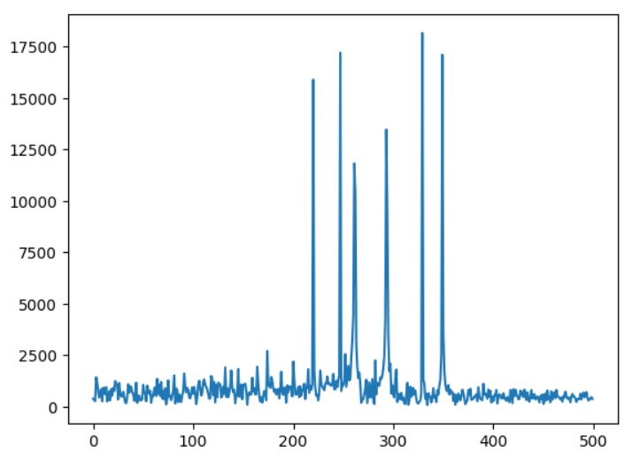
Dual YM2149 6-channel Pitch Test Frequency Spectrum Plot.
YM2149 DAC Test on Arty A7
- Hook up Digilent’s PMOD Amp2 to the upper row of the Arty A7 PMOD port JA.
- Connect a terminal program such as Putty or Teraterm to Arty’s USB serial port. Settings: 115200 8N1.
- Build the ym2149_dac_test project in an Arty A7 build tree (arty-a7-35 or arty-a7-100):
cd build/arty-a7-100/gw/projects/ym2149_dac_test make ym2149_dac_test_bit_sw - Download the generated bitstream file to the Arty A7:
make ym2149_dac_test_load - You should hear a 6-tone chord.
ST-Sound Test on Verilator
- Build the stsound_test project:
cd build/sim-a7-100/gw/projects/stsound_test make stsound_test_sim_sw - Execute the generated Verilator model. Pass in the SD card image that’s checked in as part of the test. The SD card image contains the song that we want to play. The model runs for 5s simulated time. It will take a few minutes in real-time to complete. You should see the following output:
./Vmodel -s ../../../../../gw/projects/stsound_test/test/sdcard.img SD Image File: ../../../../../gw/projects/stsound_test/test/sdcard.img SDCARD: NBLOCKS = 131072 PCM Output File: pcm_out.py XXXXXXXXXXXXXXXXXXXXXXXXXXXXXXXXXXXXXXXXXXXXXXXXXX XXX BHG_FP_clk_divider.v settings/results. XXX XXX https://github.com/BrianHGinc XXX XXXXXXXXXXXXXXXXXXXXXXXXXXXXXXXXXXXXXXXXXXXXXXXXXXXXXXXXXXXXXXXXXXXXXXXXXXXXXXXXXXXXXXXXXXXXXXXXXXXXXXXXXXXXXXXXXXXX XXX USE_FLOATING_DIVIDE = 1 XXX Set INPUT_CLK_HZ = 50000000 Hz. XXX Set OUTPUT_CLK_HZ = 2000000 Hz. XXX --------------------------------------------- (Floats only accurate to 2 decimal places) XXX True output freq = 2000000.000000 Hz. XXX Frequency error = 0.000000 ppm. XXX Periodic jitter = +/- 0.000000 ns. XXX --------------------------------------------- XXX Integer Divider = 25. XXX Divider Fraction = 0/65536. OutHz = InHz/(ID+(DF/65536)) XXX ~Divider to 6dp. = 25.000000. XXXXXXXXXXXXXXXXXXXXXXXXXXXXXXXXXXXXXXXXXXXXXXXXXXXXXXXXXXXXXXXXXXXXXXXXXXXXXXXXXXXXXXXXXXXXXXXXXXXXXXXXXXXXXXXXXXXX XXXXXXXXXXXXXXXXXXXXXXXXXXXXXXXXXXXXXXXXXXXXXXXXXXXXXXXXXXXXXXXXX XXX BrianHG's BHG_jt49_exp.v is using 10 bit DAC LUT table. XXX XXX https://github.com/BrianHGinc XXX XXXXXXXXXXXXXXXXXXXXXXXXXXXXXXXXXXXXXXXXXXXXXXXXXXXXXXXXXXXXXXXXX XXX dlut[0:31] = '{ 0, 1, 2, 3, 5, 6, 8, 11, XXX XXX 14, 17, 21, 26, 32, 39, 48, 58, XXX XXX 70, 84, 101, 121, 145, 174, 208, 248, XXX XXX 297, 354, 423, 505, 603, 719, 858, 1023} XXX XXXXXXXXXXXXXXXXXXXXXXXXXXXXXXXXXXXXXXXXXXXXXXXXXXXXXXXXXXXXXXXXX XXXXXXXXXXXXXXXXXXXXXXXXXXXXXXXXXXXXXXXXXXXXXXXXXXXXXXXXXXXXXXXXX XXX BrianHG's BHG_jt49_exp.v is using 10 bit DAC LUT table. XXX XXX https://github.com/BrianHGinc XXX XXXXXXXXXXXXXXXXXXXXXXXXXXXXXXXXXXXXXXXXXXXXXXXXXXXXXXXXXXXXXXXXX XXX dlut[0:31] = '{ 0, 1, 2, 3, 5, 6, 8, 11, XXX XXX 14, 17, 21, 26, 32, 39, 48, 58, XXX XXX 70, 84, 101, 121, 145, 174, 208, 248, XXX XXX 297, 354, 423, 505, 603, 719, 858, 1023} XXX XXXXXXXXXXXXXXXXXXXXXXXXXXXXXXXXXXXXXXXXXXXXXXXXXXXXXXXXXXXXXXXXX SDSPI: CMDIDX = 6 -- WE HAVE A COMMAND # 0! [ 40 00 00 00 00 95 ] SDSPI: Received a command 0x40 (0) arg 0x0 SDSPI: CMDIDX = 6 -- WE HAVE A COMMAND # 8! [ 48 00 00 01 a5 69 ] SDSPI: Received a command 0x48 (8) arg 0x1a5 Mounting... SDSPI: CMDIDX = 6 -- WE HAVE A COMMAND #55! [ 77 00 00 00 00 65 ] SDSPI: Received a command 0x77 (55) arg 0x0 ... SDSPI: Received a command 0x51 (17) arg 0x0 Reading from block 00000000 of 00020000 READ: Seek to sector 0 CID: 4c4f539c:47343658:03802910:c938017b SDSPI: CMDIDX = 6 -- WE HAVE A COMMAND #17! [ 51 00 00 01 04 0b ] SDSPI: Received a command 0x51 (17) arg 0x104 Reading from block 00000104 of 00020000 READ: Seek to sector 260 Listing directory contents... /ANCOOL1.YM Switching to PSG_1 SDSPI: CMDIDX = 6 -- WE HAVE A COMMAND #17! [ 51 00 00 01 30 15 ] ... READ: Seek to sector 307 Starting playback... No overflows detected. Test passed. - The Verilator model should have generated Python file pcm_out.py:
ls *.py pcm_out.py - Execute the ST-Sound Test Python script. Pass in the reference WAV file to check against. The reference WAV file is checked in as part of the test. You should hear the first few seconds of the song play. The script’s terminal output should look like this:
  PYTHONPATH="." ../../../../../gw/projects/stsound_test/test/stsound_test.py -r ../../../../../gw/projects/stsound_test/test/ref.wav
  Calculating fingerprint by fpcalc for test.wav
  Calculating fingerprint by fpcalc for ../../../../../gw/projects/stsound_test/test/ref.wav
  File A: test.wav
  File B: ../../../../../gw/projects/stsound_test/test/ref.wav
  Match with correlation of 100.00% at offset 0
(You may have to scroll the box horizontally to see the complete command line.)
ST-Sound Test on Arty A7
- Hook up Digilent’s PMOD Amp2 to the upper row of the Arty A7 PMOD port JA.
- Hook up Digilent’s MicroSD PMOD to port JD.
- Locate YM file ANCOOL1.YM in directory boxlambda/sub/StSound/YmSampleFiles/. Copy it to a FAT-formatted SD card and insert the SD card into the card reader.
- Connect a terminal program such as Putty or Teraterm to Arty’s USB serial port. Settings: 115200 8N1.
- Build the stsound_test project in an Arty A7 build tree. This test requires an Arty A7-100T. The software footprint of this test doesn’t fit in the internal memory of the Arty A7-35T build.
cd build/arty-a7-100/gw/projects/stsound_test make stsound_test_bit_sw - Download the generated bitstream file to the Arty A7:
make stsound_test_load - You should hear the chiptune play. In the terminal window you should see the following:
Mounting... CID: 534d5402:47323341:7d604971:3168018d Listing directory contents... ... /ANCOOL1.YM Switching to PSG_1 Loading YM file: ancool1.ym ... Starting playback... - There are a few controls you can play around with:
- Set SW0 (leaving SW1 and SW2 off), then press buttons 0/1 to increase/decrease the volume.
- Set SW1 (leaving SW0 and SW2 off), then press buttons 0/1 to increase/decrease the bass level.
- Set SW2 (leaving SW0 and SW1 off), then press buttons 0/1 to increase/decrease the treble level.
- SW3, sampled once at SW boot time, selects PSG0 or PSG1 to play the chiptune.
Conclusion
Sound is a complex topic, but a Programmable Sound Generator doesn’t have to be. I like the simplicity and the sound of the humble YM2149. It fits perfectly in the retro style that I’m trying to achieve with BoxLambda.
Next up is the Praxos DMA engine. Stay tuned!