Testing with Verilator.
Updated 1 May 2026: Corrected stale links. Updated 2 April 2026: Corrected stale links.
Recap
I currently have the following for BoxLambda:
- A test build for an Arty-A7-35T, consisting of an Ibex RISCV core, a Wishbone shared bus, some internal memory, a timer, two GPIO ports, and a UART core.
- A simple Hello World and LED toggling test program running on the FPGA test build.
- A Makefile and Bender-based build system with lint checking.
Testing
How should I go about testing this project? Given that this is a system integration project rather than an IP development project, I think the focus should go to system-level testing rather than component-level verification. The components themselves have already been verified by their respective owners.
Ideally, the testbench should allow for the following:
- Execute system-level test cases in a reasonable time frame. With system-level test cases, I mean test cases where the DUT is the SoC.
- A short lather-rinse-repeat cycle of making code changes and testing them on a system-level DUT.
- Full signal visibility into the build, to aid test case development as well as debugging.
- Reasonably easy automated testing. With the caveat that automated testing is never truly easy.
Using the FPGA itself as the primary system-level testbench doesn’t meet any of these criteria, other than the first one. Code changes require resynthesis. Signal visibility on the FPGA is limited. Building a robust physical testbench for automated testing is complicated.
A SystemVerilog-based testbench running on Vivado’s simulator is not an option for me either. The verification aspect of the SystemVerilog language is huge, the learning curve is steep, and the event-driven simulator is slow.
The Python-based Cocotb test bench running on the Icarus simulator is a step in the right direction. It’s easy to build powerful automated test cases in Python. A Python-based testbench running on an event-driven simulator is slow, however.
Luckily, there’s a fourth option: Verilator.
Verilator
Verilator is a compiler. It compiles, or rather verilates, an HDL design into a C++ model. It then picks up any user-provided C++ testbench/wrapper code and compiles the whole thing into an executable, optionally with the ability to generate traces. So you can run your FPGA design as an executable on your PC, and it’s fast. How cool is that!
C++ is not an ideal language for test case development, but it’ll get the job done, and it’s a compiled language, so it’s fast.
Overall, Verilator meets my test bench criteria very well.
A simple Test Bench for Hello World
I created a proof-of-concept test bench for the Hello World build. I started from the example code included in the Verilator distribution:
https://github.com/verilator/verilator/blob/master/examples/make_tracing_c/sim_main.cpp
I included UARTSIM, the UART co-simulation class that ZipCPU provides along with the UART Verilog implementation in the wbuart32 repository:
https://github.com/epsilon537/wbuart32/tree/master/bench/cpp
The test bench does the following:
- Instantiate the verilated Hello World model and the UARTSIM co-simulation object.
- Optionally, controlled by a command-line option, enable tracing.
- Run the model for a fixed number of clock cycles.
- While running the model:
- Feed the model’s UART output to UARTSIM.
- Capture and display the decoded UARTSIM output and the GPIO outputs.
- Pass/Fail criterium: After running the model for the set number of clock cycles, match the captured UART and GPIO outputs against expected results.
As suggested by ZipCPU in his Verilog tutorial, I use nCurses for positional printing inside the terminal windows. This way, I can easily build a display that refreshes, rather than scrolls, whenever the model produces new UART or GPIO data to display.
The result looks like this:
This is the test bench source code, slightly edited for brevity:
int main(int argc, char** argv, char** env) {
    std::unique_ptr<UARTSIM> uart{new UARTSIM(0)}; //Uart co-simulation from wbuart32.
    // Using unique_ptr is similar to "VerilatedContext* contextp = new VerilatedContext" then deleting at end.
    const std::unique_ptr<VerilatedContext> contextp{new VerilatedContext};

    // Verilator must compute traced signals
    contextp->traceEverOn(true);

    VerilatedFstC* tfp = new VerilatedFstC;
    bool tracing_enable = false, interactive_mode = false;

    // Command line processing
    for(;;) {
        switch(getopt(argc, argv, "ith")) {
	  case 'i':
	    printf("Interactive mode\n");
	    interactive_mode = true;
	    continue;
	  case 't':
	    printf("Tracing enabled\n");
	    tracing_enable = true;
	    continue;
	  case '?':
	  case 'h':
	  default :
	    printf("\nVmodel Usage:\n");
	    printf("-h: print this help\n");
	    printf("-i: interactive mode.\n");
	    printf("-t: enable tracing.\n");
	    return 0;
	    break;
	  case -1:
	    break;
	}
	break;
    }

    //Curses setup
    initscr(); cbreak();noecho();

    // Construct the Verilated model, from Vmodel.h generated from Verilating "ibex_soc.sv".
    const std::unique_ptr<Vmodel> top{new Vmodel{contextp.get(), "ibex_soc"}};

    //Trace file
    if (tracing_enable) {
      top->trace(tfp, 99); //Trace 99 levels deep.
      tfp->open("simx.fst");
    }

    // Set Vtop's input signals
    top->ck_rst_n = !0; top->clk100mhz = 0; top->uart_rx = 0; top->tck = 0; top->trst_n = 1;
    top->tms = 0; top->tdi = 0;

    //Initialize GPIO and UART change detectors
    unsigned char gpio0Prev = 0, gpio1Prev = 0;
    std::string uartRxStringPrev;
    std::string gpio0String; //Accumulate GPIO0 value changes as a string into this variable

    // Simulate for 10000000 timeprecision periods
    while (contextp->time() < 10000000) {
        contextp->timeInc(1);  // 1 timeprecision period passes...

        // Toggle control signals on an edge that doesn't correspond to where the controls are sampled; in this example we do
        // this only on a negedge of clk, because we know reset is not sampled there.
        if (!top->clk100mhz) {
	  if (contextp->time() > 1 && contextp->time() < 10) {
	    top->ck_rst_n = !1;  // Assert reset
	  } else {
	    top->ck_rst_n = !0;  // Deassert reset
	  }
	}

	top->clk100mhz = 1; top->eval(); // Evaluate model.
	if (tracing_enable) tfp->dump(contextp->time());

	contextp->timeInc(1);
	top->gpio1 = GPIO1_SIM_INDICATOR; //Indicate to SW that this is a simulation.
	top->clk100mhz = 0; top->eval(); // Evaluate model.
	if (tracing_enable) tfp->dump(contextp->time());

	//Feed our model's uart_tx signal and baud rate to the UART co-simulator.
	(*uart)(top->uart_tx, top->rootp->ibex_soc__DOT__wb_uart__DOT__wbuart__DOT__uart_setup);

	//Detect and print changes to UART and GPIOs
	if ((uartRxStringPrev != uart->get_rx_string()) ||
	    (gpio0Prev != top->gpio0) ||
	    (gpio1Prev != top->gpio1)) {
	  if (gpio0Prev != top->gpio0) {
	    //Single digit int to hex conversion and accumulation into gpio0String.
	    static const char* digits = "0123456789ABCDEF";
	    gpio0String.push_back(digits[top->gpio0&0xf]);
	  };

	  //Positional printing using ncurses.
	  mvprintw(0, 0, "[%lld]", contextp->time());
	  mvprintw(1, 0, "UART:");
	  mvprintw(2, 0, uart->get_rx_string().c_str());
	  mvprintw(10, 0, "GPIO0: %x", top->gpio0);
	  mvprintw(11, 0, "GPIO1: %x", top->gpio1);
	  refresh();

	  //Update change detectors
	  uartRxStringPrev = uart->get_rx_string();
	  gpio0Prev = top->gpio0; gpio1Prev = top->gpio1;
	}
    }

    //Close trace file.
    if (tracing_enable) tfp->close();

    if (interactive_mode) {
      mvprintw(15, 0, "Done.");
      mvprintw(16, 0, "Press any key to exit.");
      while (getch() == ERR);
    }

    // Final model cleanup
    top->final();
    endwin(); // End curses.

    // Checks for automated testing.
    int res = 0;
    std::string uartCheckString("Hello, World!\nThis is a simulation.\n");
    if (uartCheckString.compare(uartRxStringPrev) != 0) {
      printf("UART check failed\n");
      printf("Expected: %s\n", uartCheckString.c_str());
      printf("Received: %s\n", uartRxStringPrev.c_str());
      res = 1;
    }
    else {
      printf("UART check passed.\n");
    }

    std::string gpio0CheckString("F0F0F0F0F0F0F0F0F0F0");
    if (gpio0CheckString.compare(gpio0String) != 0) {
      printf("GPIO0 check failed\n");
      printf("Expected: %s\n", gpio0CheckString.c_str());
      printf("Received: %s\n", gpio0String.c_str());
      res = 1;
    }
    else {
      printf("GPIO0 check passed.\n");
    }

    // Return completion status. Don't use exit() or destructor won't get called
    return res;
}
projects/hello_world/sim/sim_main.cpp
Note that in the hook to the UART co-simulator object, I’m feeding it the verilated model’s UART output as well as the wbuart.uart.setup signal, which holds the current baud rate. This allows the UART co-simulator to adjust to baud rate changes. For example, at some point during the simulation, software reconfigures the baud rate from the default setting to 115200. The test bench picks that up without any trouble.
//Feed our model's uart_tx signal and baud rate to the UART co-simulator.
(*uart)(top->uart_tx, top->rootp->ibex_soc__DOT__wb_uart__DOT__wbuart__DOT__uart_setup);
I’m not taking credit for this, btw. This is all ZipCPU’s work.
Are we living in a Simulation?
Software running on Ibex needs to know whether it’s running in a simulation or on FPGA, so it can adjust timings such as the LED blink period. I’m using GPIO1 bits 3:0 for this purpose. In a simulation, I set these bits to 4’bf. On FPGA I set them to something else. hello.c now includes the following check:
  //GPIO1 bits3:0 = 0xf indicate we're running inside a simulator.
  if ((gpio_get_input(&gpio1) & 0xf) == GPIO1_SIM_INDICATOR)
    uart_printf(&uart0, "This is a simulation.\n");
  else
    uart_printf(&uart0, "This is not a simulation.\n");
Files and command line options
All files created by Verilator go in the <project_dir>/generated/ subdirectory. The name of the generated executable is Vmodel. As you can see in the sim_main.cpp source code above, Vmodel accepts a few command line options:
- Vmodel -t: Execute with waveform tracing enabled. The program generates a .fst trace file in the current directory. .fst files can be viewed with gtkwave.
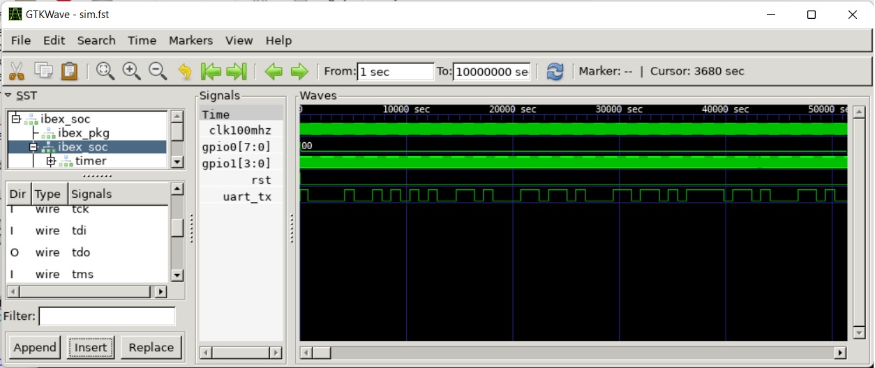 Gtkwave View of Waveform Trace Generated by *Hello World Verilator Test Bench*
- Vmodel -i: Run in interactive mode, vs. the default batch mode. In interactive mode, the program may wait for keypresses. Batch mode is used for non-interactive automated testing.
Performance
The real-time-to-simulated-time ratio of the Hello World model executing without tracing is 70.
The real-time-to-simulated-time ratio of the Hello World model executing with tracing is 750.
Verilator issues a couple of UNOPTFLAT warnings during verilation. UNOPTFLAT issues significantly affect performance (but not functionality). These issues can be fixed by changing the HDL code a little to make it more Verilator-friendly. The current model is plenty fast for me, however. I have filed the UNOPTFLAT issue as a note-to-self issue on GitHub.
New Build System Targets
- In a project directory:
- make sim: builds the project’s Verilator test bench.
- make test: builds the project’s Verilator test bench, then runs it in batch mode (non-interactive mode).
- In the root directory:
- make test: recursively builds and runs the Verilator test bench in each project directory. make test fails if any of the executed test benches flag a test failure (via a non-zero return code).
Try It Out
To try out the proof-of-concept Verilator Test Bench:
- Install the prerequisites.
git clone https://github.com/epsilon537/boxlambda/cd boxlambda- Switch to the testing_with_verilator tag:
git checkout testing_with_verilator - Get the submodules:
git submodule update --init --recursive - Build the testbench:
cd projects/hello_worldmake sim
- Execute the testbench:
cd generated- Without tracing (fast):
./Vmodel -i - With tracing (slow):
./Vmodel -t
- View the generated traces:
gtkwave simx.fst
Interesting Links
https://projectf.io/: An great website/Blog by Will Green about learning FPGA development with graphics. In this post, Will Green shows how to hook up a Verilator-based test bench to SDL. That’s a nice option to keep in mind when I get around to integrating VERA into BoxLambda.