On USB HID, Keyboard LEDs, and device emulation.
Updated 2 April 2026: Corrected stale links.
Updated 23 December 2025: Removed reference to ‘On WSL’ documentation.
I added keyboard and mouse support to BoxLambda. The plan was to use PS/2, but when NAND2Mario announced their usb_hid_host core, I couldn’t resist. I added a Wishbone frontend and some CDC logic to cross from the 12MHz USB clock domain to the 50MHz system clock domain. I plugged in a keyboard and mouse, and it all worked fine. End of story…
Almost. The original usb_hid_host core does not include support for controlling USB keyboard LEDs. Adding that feature required a deep dive into the usb_hid_host implementation and the USB spec. I also needed a way to test it all in simulation, in other words, I needed a USB keyboard and mouse emulator.
Recap
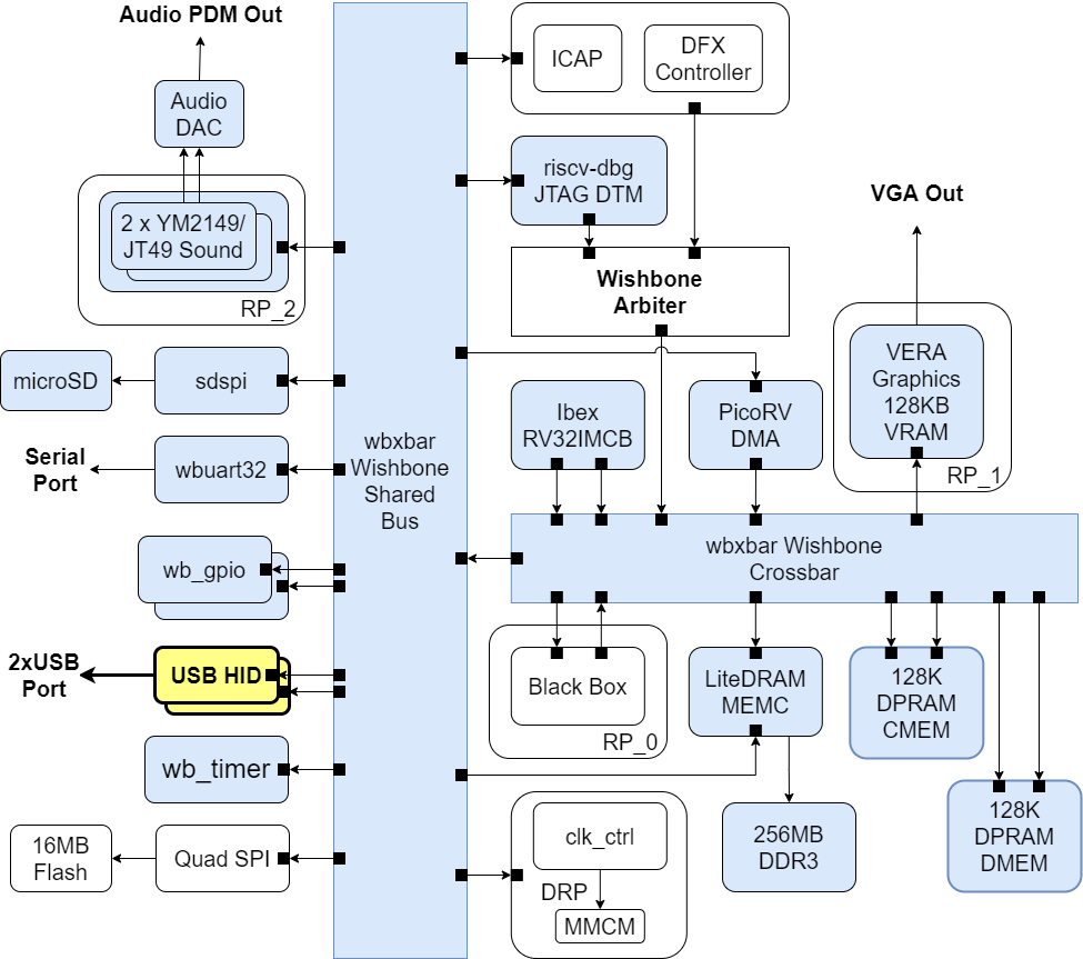
This is a summary of the current state of affairs for BoxLambda. We have:
- An Ibex RISC-V core, Wishbone Interconnect, timer, two GPIO ports, UART core, and internal memory.
- DDR3 external memory access through the Litex Memory Controller.
- OpenOCD-based Debug Access, both on FPGA and Verilator.
- VERA-based VGA graphics: 2 layers tile or bitmap mode, 2 banks of 64 sprites, 128KB Video RAM, 256 color palette.
- Dual YM2149 PSG Audio.
- SD Card Controller and FatFs File System.
- A PicoRV32-based Programmable DMA Controller.
- A Picolibc-based standard C environment for software running on the Ibex RISC-V core.
- Test builds running on Arty-A7-35T, Arty-A7-100T, Verilator, and CocoTB.
- A Linux CMake and Bender-based Software and Gateware build system with support for automated testing and post-implementation memory updates.
The NAND2Mario usb_hid_host core
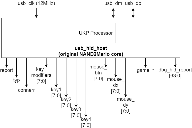
The NAND2Mario usb_hid_host core.
The NAND2Mario usb_hid_host core is easy to use. You don’t need a USB software stack. UKP, a little 4-bit processor inside the core handles the USB enumeration. You don’t need a USB PHY chip either. You can just hook up the USB D-/D+ pins directly to a simple USB PMOD. I’m using the following PMOD from Machdyne:
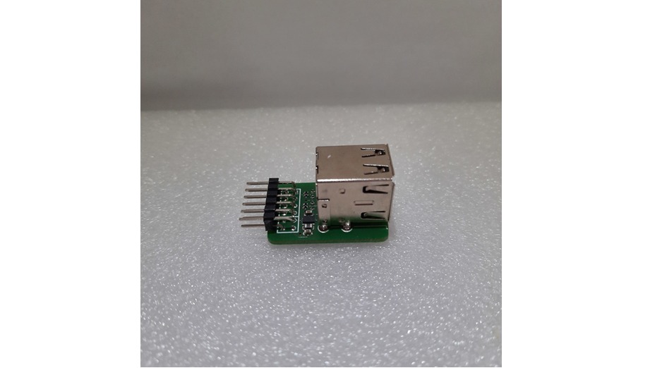
The Machdyne USB host dual socket PMOD.
https://machdyne.com/product/usb-host-dual-socket-pmod/
Usb_hid_host requires a 12MHz clock. You just hook up the clock, reset, USB D-/D+ and the core takes care of the rest. Usb_hid_host has the following output ports:
- report: a strobe signal indicating that a new report has been received from the attached device (e.g. a key press, a mouse movement,…).
- typ: the type of the attached USB device: keyboard, mouse, or gamepad.
- connerr: a connection error indication.
- key_modifiers: if the attached device is a keyboard, indicates which key modifiers (ctrl, shift,…) are being held down.
- key1-4: if the attached device is a keyboard, indicates which non-modifier keys are being pressed, with a max. of 4 keys being pressed simultaneously.
- mouse_btn: if the attached device is a mouse, indicates which mouse buttons are being pressed.
- mouse_dx: if the attached device is a mouse, indicates the mouse’s horizontal movement.
- mouse_dy: if the attached device is a mouse, indicates the mouse’s vertical movement.
- game_*: if the attached device is a gamepad, indicates the gamepad joystick directions and buttons being pressed. I haven’t tested these yet. I currently don’t have a gamepad.
- dbg_hid_report: the raw HID report, for debug purposes.
USB HIDBP
The USB HID Spec is big and complicated. A complete implementation would require a lot more infrastructure than just a small usb_hid_host core. Usb_hid_host implements a subset of the USB HID spec called the Boot Protocol (USB HIDBP). The Boot Protocol was added to the spec to humor BIOS developers. The Boot Protocol is much simpler than its counterpart, the Report Protocol, which is the protocol used by the big USB stacks in Linux or Windows.
Unfortunately, not all keyboards and mice support the Boot Protocol. Basic/Low-end keyboards and mice have a higher chance of supporting the Boot Protocol. I’m using a Dell KB212-B keyboard and a Dell OCJ339 mouse.
Controlling USB keyboard LEDs
I want to add keyboard LED control to the NAND2Mario core. Where to start?
The best information I could find online describing USB HID in general, and keyboard LED control in particular, is this page from the OSDev Wiki:
https://wiki.osdev.org/USB_Human_Interface_Devices.
For the lower-level details, e.g. how to set up a Control Transfer to the device, I found USB in a nutshell very helpful.
Briefly, the USB host controls keyboard LEDs by sending a SetReport message to the device using a Control Transfer. The message contains a bitmap specifying which LEDs should be on and off.

SetReport Keyboard LED bitmap.
The entire packet sequence looks like this:
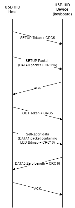
SetReport Sequence Diagram.
Quite an elaborate sequence to control a few LEDS!
Adding USB keyboard LED control to the usb_hid_host core
UKP processor inside the usb_hid_host core just recognizes a handful of instructions that are specifically created to detect and enumerate USB devices. The original instruction set is documented here. Note that there are no instructions that respond to external inputs other than what comes in over USB. To implement keyboard LED control, I need a way to branch to a SetReport routine based on an external signal and a way to configure the contents of the SetReport message.
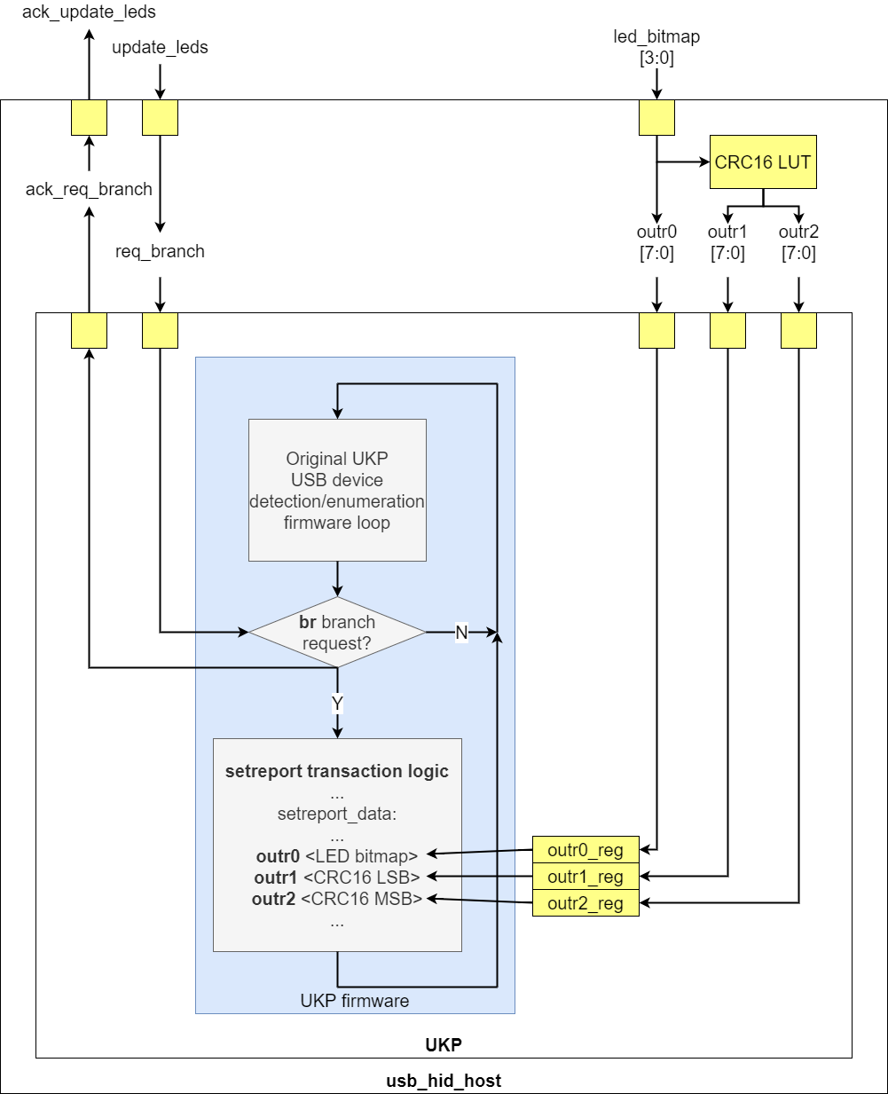
Keyboard LED control in the usb_hid_host core.
To add USB keyboard LED control to the usb_hid_host core, I implemented the following changes in the UKP processor:
- I extended the UKP opcode width from 4 bits to 5 bits. This gave me space to add new instructions.
- I added a conditional Branch Request (br) instruction and a req_branch_stb input port to the UKP module. Through the req_branch_stb signal, the user (usb_hid_host) can request the branch to be taken. When the branch has been taken, an ack_req_branch_stb is sent back to the user.
- I added outr0, outr1, and outr2 instructions, associated with three 8-bit registers and three 8-bit input ports of the UKP module, also called outr0, outr1, and outr2. When an outr
instruction executes, the contents of the associated register will be transmitted over the USB port.
With these UKP changes, the usb_hid_host core can, upon request, have the UKP firmware branch to a section of microcode that sends a SetReport request to the device. The parameters of this message, i.e. the LED bitmap and the CRC16 value are specified in outr0 and outr1/2.
As an aside, since the variable portion of the SetReport message is just 4 LED bits (I left out KANA, sorry!), I’m using a CRC16 look-up table to find the CRC16 value of the SetReport message, rather than a CRC16 generator. I used this handy website to compute the necessary CRC16 and CRC5 values used in the SetReport transaction:
The usb_hid_host fork with keyboard LED control support is located here:
https://github.com/epsilon537/usb_hid_host
Wishbone Frontend and Clock Domain Crossing
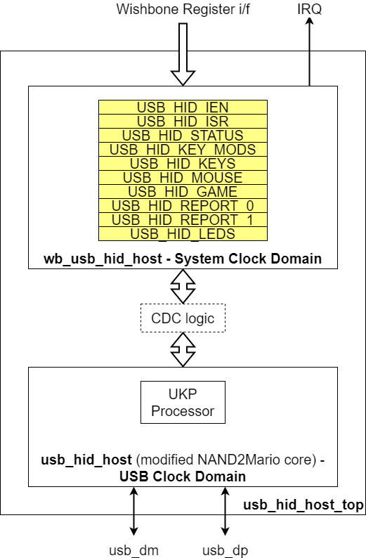
Usb_hid_host core in USB Clock Domain with Wishbone Frontend in System Clock Domain.
I added a Wishbone frontend to the usb_hid_host core so it could be integrated into the BoxLambda SoC. The BoxLambda SoC system clock runs at 50MHz while the usb_hid_host core runs at 12MHz, so Clock Domain Crossing (CDC)) logic is needed between these two clock domains. I struggled with that for a bit, until I read this paper:
http://www.sunburst-design.com/papers/CummingsSNUG2008Boston_CDC.pdf
If you haven’t read this paper and you’re messing around with CDC in your projects, don’t waste your time reading this post. Go read that paper. You’ll feel much better!
I found the toggle-pulse generation technique in Figure 20 of the document very elegant. You can bring a single clock cycle pulse/strobe from one clock domain to another by turning the pulse into a toggle in the transmitting clock domain, synchronizing the toggle to the receiving clock domain, and then turning the toggle back into a pulse.
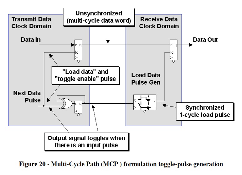
MCP CDC technique using Toggle-Pulse.
In both directions, USB to System Clock and System Clock to USB, I’m using a Multi-Cycle Path (MCP) strategy to pass signals across the clock domains. In the System Clock to USB direction (fast to slow clock), I’m using feedback. Keyboard LED update requests are acknowledged.
USB HID Device Emulation
To test the usb_hid_host core in simulation, I have to connect it to an emulated USB HID device. In a dusty corner of GitHub, I found this gem:
This is a project from Pbing, the author of the ibex_wb project that I used to bootstrap BoxLambda.
Pbing’s USB project emulates a mouse. The design is based on a J1 processor executing Forth-based firmware. How cool is that?
Forth and J1
I don’t know how I’ve managed to overlook Forth and J1 all this time. Here’s a great post on Hacker News about Forth and The J1 Forth CPU:
https://news.ycombinator.com/item?id=25759576
Forth is very efficient and very elegant. It allows you to interactively write fast and powerful code, a couple of notches above assembly level, without requiring heavy cross-compiling toolchains and VMs. SwapForth, an interactive Forth development environment, runs easily on a J1a CPU with 8KB of RAM. I’m amazed and will be exploring further.
The Simulation Setup
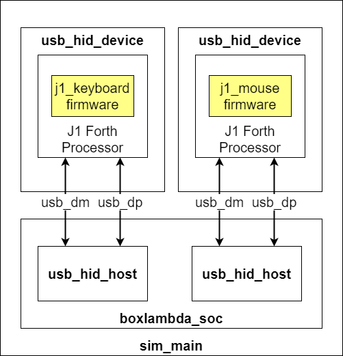
USB HID System Test Simulation Setup.
To test USB mouse support, I’m using Pbing’s mouse emulation as-is. To test USB keyboard support, I created a firmware variant that emulates a keyboard with a key being pressed. The firmware also accepts the SetReport messages for LED control and will set GPIOs depending on the value of the received LED bitmap.
The simulation top-level, sim_main.sv, hooks up the mouse and the keyboard emulations to the two usb_hid_host instances of the BoxLambda SoC. Sim_main.sv includes logic tracking the USB ports’ output enables and driving the USB D+/D- lines high or low to emulate the pull-up/pull-down behavior of a low-speed USB device (See https://www.beyondlogic.org/usbnutshell/usb2.shtml#SpeedIdentification).
The usb_hid_device repo
This is a fork of Pbing’s USB repo including USB keyboard emulation:
https://github.com/epsilon537/usb_hid_device
Clocks and Reset
The usb_hid_host cores introduce a new clock and reset domain to the BoxLambda SoC.
The clock tree currently looks like this:
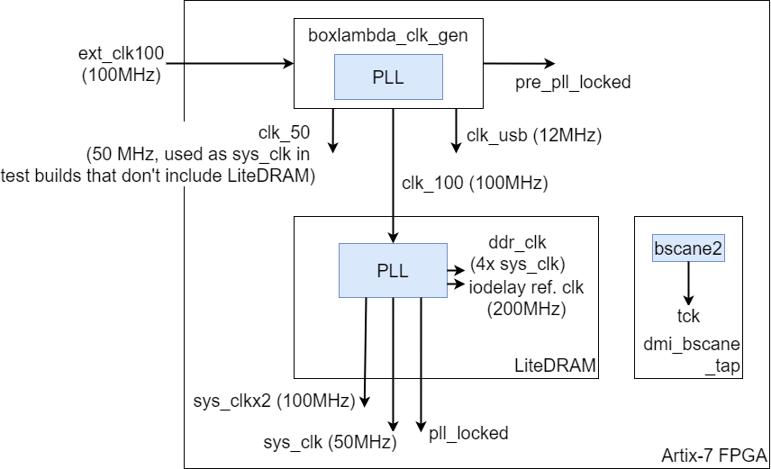
BoxLambda’s Clocks.
The following clocks are present in the SoC:
- ext_clk_100: 100MHz external clock, input to the LiteDRAM core.
- sys_clk: 50MHz System Clock, generated by the LiteDRAM core, used by rest of SoC (CPU, Interconnect,…).
- sys_clkx2: 100MHz Double Rate System Clock, generated by the LiteRAM core, twice the rate of, and in phase with sys_clk. Sys_clkx2 is used by the PicoRV core.
- ddr_clk: SDRAM DDR PHY clock running at 4xsys_clk, generated by the LiteDRAM core.
- 200MHz reference clock for IODELAYs, generated and used the LiteDRAM core.
- tck: JTAG clock, driven via a BSCANE2 primitive by the FPGA’s JTAG chain. The BSCANE2 primitive is instantiated in the dmi_bscane_tap module.
- usb_clk: 12MHz clock for the USB HID Host cores.
BoxLambda has three synchronous Reset Domains:
- dm_reset: Resets the Debug Module Logic in the system clock domain.
- ndm_reset: Resets the Non-Debug Module Logic in the system clock domain.
- usb_reset: Resets the logic in the USB clock domain.
and the following Reset Sources:
- Power-On Reset: Asserted for several clock cycles after Power-On.
- External Reset: Connected to a reset button on the Arty A7 board.
- Non-Debug Module Reset Request: issued by the Debug Module.
- Software Reset: Reset of dm_reset, ndm_reset, or usb_reset domain triggered by software by writing to a reset_ctrl register.
The management of these reset domains and reset sources is organized by a reset_ctrl module.
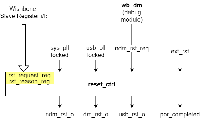
BoxLambda’s Reset Controller.
The reset_ctrl module code is located here:
https://github.com/epsilon537/boxlambda/blob/usb_hid_host/gw/components/reset_ctrl/rtl/reset_ctrl.sv
Software
The USB HID HAL
The USB HID HAL is a very thin Hardware Access Layer, mapping directly to the two USB cores’ registers:
https://github.com/epsilon537/boxlambda/blob/usb_hid_host/sw/components/usb_hid/usb_hid_hal.h
The USB HID System Test Case
The USB HID System Test Case, running both on Verilator and on FPGA, continuously polls the two USB cores for report events. Whenever there’s a report event (indicated in the USB_HID_ISR register), the device type (Keyboard/Mouse) and report details (mouse movement, keypress…) are printed.
Additionally, when Switch 0 (SW0) is set to On and a USB keyboard is connected, the keyboard LEDs will be turned on and off in a rotating pattern.
The usb_hid_host firmware
The usb_hid_host UKP firmware .hex image is checked in, so you don’t need to build it from source.
If you would like to tinker with the firmware, you’ll need to have perl installed (sudo apt-get install perl on Ubuntu).
UKP Firmware directory: sub/usb_hid_host/src/usb_hid_host/
After making your changes, run the asukp script in that same directory and a new firmware image will be generated.
The usb_hid_device firmware
The usb_hid_device firmware .hex images for the emulated keyboard and mouse are checked in, so you don’t need to build them from source.
If you would like to tinker with the firmware, you’ll need to install gforth (sudo apt-get install gforth on Ubuntu). The firmware is located here:
- Mouse Firmware directory: sub/usb_hid_device/firmware_mouse/
- Keyboard Firmware directory: sub/usb_hid_device/firmware_keyboard/
After making your changes, just run make in that same directory and a new firmware image will be generated.
Try It Out
Setup
- Install the Software Prerequisites.
- Get the BoxLambda repository:
git clone https://github.com/epsilon537/boxlambda/ cd boxlambda - Switch to the usb_hid_host tag:
git checkout usb_hid_host - Set up the repository. This initializes the git submodules used and creates the default build trees:
./boxlambda_setup.sh
The USB HID Test on Verilator
- Build the usb_hid_sys_test project:
cd build/sim-a7-100/gw/projects/usb_hid_sys_test make usb_hid_sys_test_sim_sw - Execute the generated Verilator model. You should see the following output (it’ll take a minute before you start seeing any output):
./Vmodel
...
USB HID Test Start.
USB1: Status change: 0x0 -> 0x1
  Keyboard detected.
ledg_1 = 2
USB1 keyboard report: 0x210900001000100
  Key mods: 0x0 Keys: 0x0
USB0: Status change: 0x0 -> 0x2
  Mouse detected.
USB0 mouse report: 0xcffcfc001000100
  Mouse: 0x0
USB1 keyboard report: 0x400000
  Key mods: 0x0 Keys: 0x4
USB0 mouse report: 0xcffcfc001000100
  Mouse: 0x0
...
Test passed.
The ledg_1 = … lines indicate a LED update in the emulated USB keyboard.
The USB HID Test on FPGA
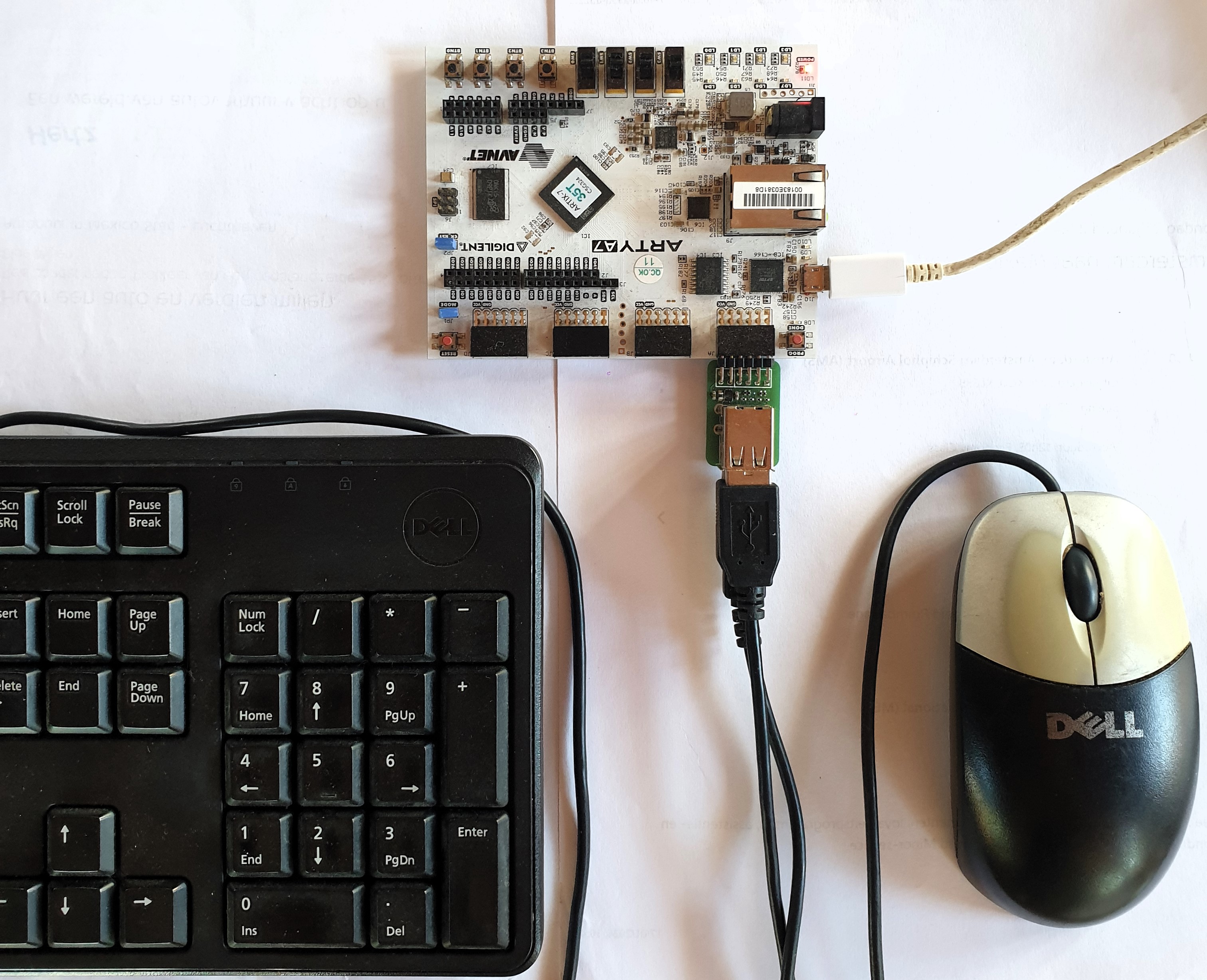
Arty A7 Setup with USB PMOD attached to port JA.
- Hook up Machdyne’s USB host dual socket PMOD to port JA and connect a keyboard and/or a mouse.
- Connect a terminal program such as Putty or Teraterm to Arty’s USB serial port. Settings: 115200 8N1.
- Build the project in an Arty A7 build tree (arty-a7-35 or arty-a7-100):
cd build/arty-a7-100/gw/projects/usb_hid_sys_test make usb_hid_sys_test_bit_sw - Download the generated bitstream file to the Arty A7:
make usb_hid_sys_test_load - Make sure Switch 0 (SW0) is in the Off position (flipped toward the edge of the board).
- Press some keys on the keyboard, move the mouse around. You should see the results in the Putty terminal.
- Flip SW0 on.
- You should now see the keyboard LEDs rotate.
https://youtube.com/shorts/qZe9CCA0zFE?feature=share
Conclusion
NAND2Mario made it very easy to interface an FPGA design to a USB keyboard and mouse, without requiring a ton of logic and infrastructure. I could have wrapped up the integration exercise in a couple of days or less. Adding keyboard LED control support gave me the perfect excuse to dive a little deeper. When you look under the hood, it becomes clear that it’s quite tricky to achieve the simple user interface that usb_hid_host provides.
Where the usb_hid_host core took the approach of using a tiny UKP processor with a very limited special-purpose instruction set, Pbing’s usb_hid_device core uses a J1 processor running Forth! I’m impressed by the elegance of Pbing’s approach. I have J1 and Forth on my radar now!
References
CDC Design and Verification Techniques Using SystemVerilog.
The original NAND2Mario usb_hid_host repo
The usb_hid_host repo fork with keyboard LED control support