An attempt at a PicoRV32-based Soft DMA Controller.
Updated 2 April 2026: Corrected stale links.
Updated 13 November 2023: Corrected performance number:
- Bus utilization for 4x unrolled wordcopy is 25%, not 30%.
- Fixed broken picorv_dma tag.
Updated 23 December 2025:
- Corrected link to architecture diagram in documentation.
- Removed reference to ‘On WSL’ documentation.
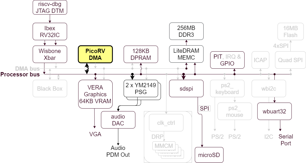
The PicoRV-based DMA Controller in the BoxLambda Architecture.
I added a processor-based DMA Controller to BoxLambda. The goal is to use it for data transfers between external and internal memory and to assist the CPU with use cases such as graphics blitting, audio playback, and file I/O. These use cases require a lot of flexibility:
- Multiple data widths: bytes, 16-bit half-words, 32-bit words.
- Differences in data width between source and destination.
- Multiple data alignment scenarios: all possible combinations of word-aligned and unaligned sources and destinations.
- Different block sizes and strides, both in source and destination.
- Scatter-Gather.
- Bit manipulations such as bit-masking and rotation on the data being transferred.
Hence the processor-based approach. I started with the Praxos DMA controller but was unhappy with the outcome. To address the shortcomings I saw with Praxos, I moved to the PicoRV32 RISC-V processor. This works well, but as you’ll see, in its current form it’s slow.
Recap
This is a summary of the current state of affairs for BoxLambda. We have:
- An Ibex RISC-V core, Wishbone shared bus, timer, two GPIO ports, UART core, and internal memory.
- DDR3 external memory access through the Litex Memory Controller.
- OpenOCD-based Debug Access, both on FPGA and Verilator.
- VERA-based VGA graphics: 2 layers tile or bitmap mode, 2 banks of 64 sprites, 128KB Video RAM, 256 color palette.
- Dual YM2149 PSG Audio.
- SD Card Controller and FatFs File System.
- A Picolibc-based standard C environment for software running on the Ibex RISC-V core.
- Test builds running on Arty-A7-35T, Arty-A7-100T, and Verilator.
- A Linux CMake and Bender-based Software and Gateware build system with support for automated testing and post-implementation memory updates.
Transfer Scenarios
If the DMA Controller is to assist in graphics blitting, audio playback, and file I/O use cases, a great deal of flexibility is required. Example transfer scenarios include, but are not limited to:
- Multiple data widths and differences in data width between source and destination.: bytes, 16-bit half-words, 32-bit words.
- Multiple data alignment scenarios: all possible combinations of word-aligned and unaligned sources and destinations.
- Different block sizes and strides, both in source and destination.
- Scatter-Gather.
- Flow Control and Rate Control.
- Bit manipulations such as bit-masking and rotation on the data being transferred.
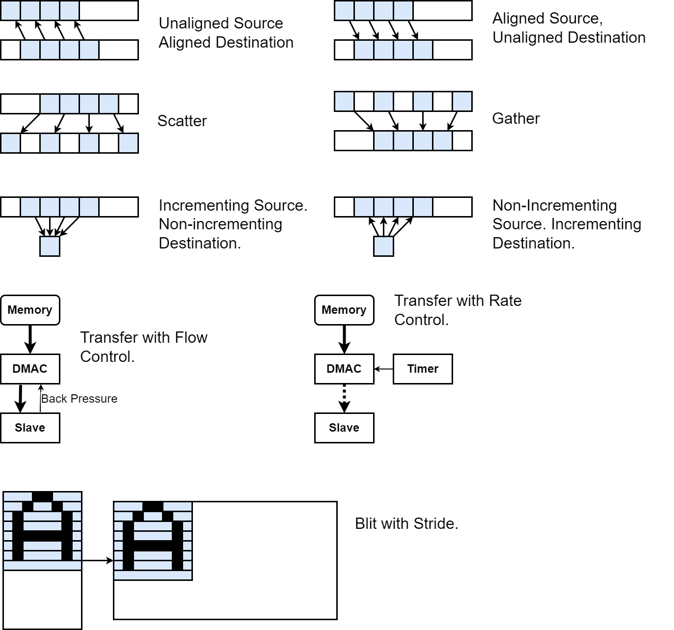
Example DMA Transfer Scenarios.
With a processor-based DMA Controller, these scenarios can easily be implemented through a simple assembly program handling load and store pointer manipulations, ALU operations on the data being moved, and IRQ-driven flow and rate control.
The PicoRV DMA Core Block Diagram
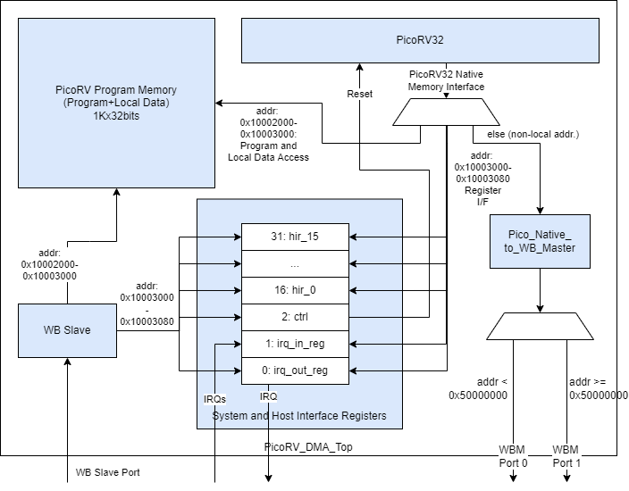
The PicoRV DMA Core Block Diagram.
The DMA core’s top-level is located here:
Memory accesses coming from the PicoRV processor are mapped into three address spaces:
- 0x10002000-0x10003000: PicoRV Program Memory, or to be more accurate, Program Memory and Local Data.
- 0x10003000-0x10003080: The DMA Core’s System Registers and Host Interface Registers (HIR), not to be confused with PicoRV’s own registers (x0-x31).
- All other memory accesses are considered non-local and are turned into Wishbone Bus Master (WBM) transactions. These WBM transactions are dispatched to WBM port 0 or port 1 based on a cut-off address (0x50000000). The intent is to attach port 0 to the Processor Bus and port 1 to the DMA Bus. See BoxLambda’s Architecture Diagram.
These address spaces match with the world view of BoxLambda’s Ibex RISC-V host processor.
Through the Wishbone Slave (WBS) port, the Host Processor has access to PicoRV’s Program Memory, the System Registers, and the Host Interface Registers.
Host processor access to PicoRV’s Program Memory is only enabled when the PicoRV is held in reset. PicoRV reset is controlled through one of the System Registers, the Control Register.
The 16 Host Interface Registers serve as the communication interface between the Host Processor and the DMA Controller. They are general-purpose registers. Their role is decided by the program that gets loaded into PicoRV’s Program Memory.
System Registers IRQ_in and IRQ_out are for interrupt handling and interrupt reporting respectively:
- IRQ_in register: System interrupts get registered here. The PicoRV itself is configured without interrupt handling support. Instead, the program loop is expected to poll the IRQ_in register if interrupt handling is required.
- IRQ_out register: The PicoRV can set IRQs in this register. If any bits in the IRQ_out register are set, the core sets the irq_out output signal.
Usage
The intended usage is as follows:
- The Host Processor loads an application-specific microprogram into the DMA core.
- The PicoRV executes from its own Program Memory. This is expected but not enforced. The PicoRV can fetch instructions from external memory through the bus master ports.
- The Host Processor configures DMA requests and the PicoRV reports status through the Host Interface Registers. The role of the different registers is determined by the application-specific microprogram running on the PicoRV.
- Flow Control can be implemented through interrupts, or by having the PicoRV poll the given slave using the slave’s register interface.
- Rate Control can be implemented through interrupts or PicoRV internal timing.
Note that although I primarily intend to use the PicoRV DMA core for DMA purposes, it can be used as a general-purpose auxiliary processor as well. All it takes is to load a microprogram that consists of a single jump to the main program in on-chip or external memory.
Utilization on Arty A7
| Slice LUTs | Slice Registers | Block RAM tiles | DSPs |
|---|---|---|---|
| 2088 | 1230 | 1 | 0 |
Example
A simple word copy microprogram can look like this:
.include "picoasm_hal.h"
/*Word Copy test program*/
    .text
    .balign 4
    .globl _start
    /*Status register values*/
    .equ STAT_START, 1
    .equ STAT_BUSY, 3
    .equ STAT_DONE, 0
_start:
    li a0, HIR_REGS_BASE_ADDR
wait_start:
    lw a1, HIR3(a0)   /*HIR3: ctrl-status*/
    beqz a1, wait_start
    li a1, STAT_BUSY
    sw a1, HIR3(a0)   /*set status to 'Busy'*/
    lw a1, HIR0(a0)    /*HIR0: src pointer*/
    lw a2, HIR1(a0)    /*HIR1: dst pointer*/
    lw a3, HIR2(a0)    /*HIR2: num words*/
    slli a3, a3, 2    /*Multiple by 4 to convert to byte address offset.*/
    add a3, a3, a1
loop:
    /*Copy word by word*/
    lw t0, 0(a1)
    sw t0, 0(a2)
    addi a1, a1, 4
    addi a2, a2, 4
    bltu a1, a3, loop
    sw zero, HIR3(a0) /*set to 'Done'*/
    j wait_start
The Ibex host processor program loads the microprogram binary into the DMA core and takes the core out of reset using a simple HAL-level API:
picorv_load_program(picorv_wordcopy_picobin, picorv_wordcopy_picobin_len);
picorv_sys_reg_wr(PICORV_SYS_REG_CTRL, 1);
Once this is done, the PicoRV DMA controller behaves just like a very basic, hardwired DMA controller. From the host processor, you configure the source and destination address, a number of words to copy, and you kick it off.
picorv_gp_reg_wr(PICORV_GP_REG_SRC, (unsigned)src);
picorv_gp_reg_wr(PICORV_GP_REG_DST, (unsigned)dst);
picorv_gp_reg_wr(PICORV_GP_REG_NUM_ELEMS, numElems);
printf("Kicking off DMA...\n");
picorv_gp_reg_wr(PICORV_GP_REG_CTRL_STAT, DMA_START);
printf("Waiting for completion...\n");
int dmaBusy = DMA_BUSY;
while(dmaBusy)
    dmaBusy = picorv_gp_reg_rd(PICORV_GP_REG_CTRL_STAT);
.Picoasm - CMake Build Support for PicoRV Assembly Code
Although Ibex and PicoRV32 are both 32-bit RISC-V processors, the programming model for the two is very different. For Ibex, I build and run C/C++ code, and use the riscv-unknown-elf-gcc frontend for compilation and linking. For PicoRV, I write tiny assembly programs. I use riscv-unknown-elf-as for assembling and riscv-unknown-elf-ld for linking. Hence, I decided to set up separate CMake toolchain variables for PicoRV code. I did this by creating an ASM_PICO assembler dialect as described in this article from Kitware:
https://gitlab.kitware.com/cmake/community/-/wikis/doc/cmake/languages/Assembler
The article tells you to create three files in the CMake modules directory. Here are the files I created for ASM_PICO:
https://github.com/epsilon537/boxlambda/tree/picorv_dma/cmake
I needed to come up with a new filename extension for PicoRV assembly files because CMake toolchain selection is done based on the filename extension. I decided to go for .picoasm for the source code and .picobin for the generated binaries.
Testing
Unit Testing with CoCoTB
I created a unit test for the PicoRV DMA core. I could have done this in C/C++ using Verilator, as I did for previous BoxLambda work, but I’ve been looking for an opportunity to try out CocoTB. CocoTB is a Python-based verification framework. It’s very easy to pick up. Your Python test script operates directly on a DUT (Device Under Test) object. No boilerplate code is required to get it going. All the interaction with the simulator is handled behind the scenes.
You monitor signals using triggers such as RisingEdge(dut.wbm.stb), and you drive signals by setting their value, e.g. dut.wbs.sel.value = 0xf. This can all be done concurrently using asynchronous tasks, which you create and execute as easily as executing functions. For example:
#Asynchronous task deasserting WB STB signal when slave no longer stalls.
async def wb_stall_check(dut):
    await RisingEdge(dut.clk)
    if dut.wbs_stall.value == 1:
        await FallingEdge(dut.wbs_stall)
    dut.wbs_stb.value = 0

async def wb_read(dut, addr):
    ...
    stall_check_task = cocotb.start_soon(wb_stall_check(dut))

    ackDetected = False
    while not ackDetected:
        await RisingEdge(dut.clk)
        if dut.wbs_ack.value == 1:
            #dut._log.info("WBS: ack detected")
            ackDetected = True

    stall_check_task.kill()
    assert dut.wbs_err.value == 0
    res = dut.wbs_dat_r.value

    await RisingEdge(dut.clk)
    dut.wbs_cyc.value = 0
A CocoTB test module consists of one or more test cases that get discovered automatically by the framework. Here is my CocoTB test module for the PicoRV DMA core:
Depending on the test case, the test script will load a different Picoasm program into to core. The Picoasm test programs are located here:
https://github.com/epsilon537/boxlambda/tree/picorv_dma/sw/components/picorv_dma/test
Please be aware that I’m an absolute newbie when it comes to CocoTB. Do not take that script as an example of a ‘good’ CocotB test module. I’m pretty sure that if I look back at this script after getting more experience with the tool, I’ll cringe. Anyway, this is what I was able to whip with my current understanding of CocoTB. It works and it was a big help to get the core up and running. It was a pleasure to write the test cases. Writing Python code is just much easier, faster, and less tedious than writing in C/C++, or Verilog.
I’m using Icarus as the behind-the-scenes simulator for CocoTB. CocoTB does support Verilator, but that’s still in an experimental phase.
I intend to keep my SoC-level system test cases in Verilator, because a Verilator model runs so fast. For unit testing, however, CocoTB is now my go-to platform.
CocoTB Test Case Execution and Dependencies.
I execute the CocoTB test in the build tree as a CMake test. However, the test script loads various PicoRV binaries into the core, and those binaries need to be built before the test can execute. The easiest way I could find to make that work was to add a picorv_dma_test build target to the module’s CMakeLists.txt. The target just lists all the used PicoRV binaries as dependencies. I would run the build step first and then execute the test.
The CMakeLists.txt looks like this:
add_custom_target(picorv_dma_test ALL
        WORKING_DIRECTORY
            ${CMAKE_CURRENT_BINARY_DIR}
        COMMENT
            "Dummy target to collect test dependencies."
        DEPENDS
            picorv_wr_hir_regs
            picorv_hir_regs_copy
            picorv_irq_in_out
            picorv_wordcopy
            picorv_bytecopy
            picorv_progmem_data_access
        VERBATIM
    )

add_test(NAME picorv_dma_cocotb_test
    COMMAND ${PROJECT_SOURCE_DIR}/scripts/cocotb_test.sh ${CMAKE_CURRENT_LIST_DIR}/test/picorv_dma_test.py
    WORKING_DIRECTORY ${CMAKE_CURRENT_BINARY_DIR}
)
Building and executing the test:
~/work/boxlambda/build/sim-a7-100/gw/components/picorv_dma$ make picorv_dma_test
[ 25%] Built target picorv_progmem_data_access
[ 50%] Built target picorv_wr_hir_regs
[ 50%] Built target picorv_hir_regs_copy
[ 75%] Built target picorv_irq_in_out
[ 75%] Built target picorv_wordcopy
[ 75%] Built target picorv_bytecopy
[100%] Dummy target to collect test dependencies.
[100%] Built target picorv_dma_test
~/work/boxlambda/build/sim-a7-100/gw/components/picorv_dma$ ctest -V
...
1: Test command: /home/epsilon/work/boxlambda/scripts/cocotb_test.sh "/home/epsilon/work/boxlambda/gw/components/picorv_dma/test/picorv_dma_test.py"
1: Working Directory: /home/epsilon/work/boxlambda/build/sim-a7-100/gw/components/picorv_dma
1: Test timeout computed to be: 10000000
1: Script directory: /home/epsilon/work/boxlambda/scripts
1: PYTHONPATH: .:/home/epsilon/work/boxlambda/scripts:
1:      -.--ns INFO     gpi                                ..mbed/gpi_embed.cpp:76   in set_program_name_in_venv        Did not detect Python virtual environment. Using system-wide Python interpreter
1:      -.--ns INFO     gpi                                ../gpi/GpiCommon.cpp:101  in gpi_print_registered_impl       VPI registered
1:      0.00ns INFO     cocotb                             Running on Icarus Verilog version 13.0 (devel)
1:      0.00ns INFO     cocotb                             Running tests with cocotb v1.9.0.dev0 from /home/epsilon/oss-cad-suite/lib/python3.8/site-packages/cocotb-1.9.0.dev0-py3.8-linux-x86_64.egg/cocotb
1:      0.00ns INFO     cocotb                             Seeding Python random module with 1695898255
1:      0.00ns INFO     cocotb.regression                  Found test picorv_dma_test.picorv_reset
1:      0.00ns INFO     cocotb.regression                  Found test picorv_dma_test.wbs_access_to_program_memory
...
1:      0.00ns INFO     cocotb.regression                  running picorv_reset (1/8)
...
System Testing
In the system test case, a test program running on the host processor configures the DMA controller to perform a word copy and a byte copy from various sources to various destinations, including internal memory, external memory, and video RAM. Both bus master ports are exercised. By doing this, the system test exercises:
- DMA Controller program loading.
- DMA Controller reset.
- Communication with the DMA Controller using Host Interface Registers.
- The DMA controller Wishbone slave port.
- The DMA controller Bus Master operation on both bus master ports.
The System Test SoC is located here:
The System Test Software is here:
https://github.com/epsilon537/boxlambda/blob/picorv_dma/sw/projects/picorv_dma_sys_test/main.c
Performance
This is the waveform of the DMA core copying words from port 0 to port 1, using the naive word copy program:
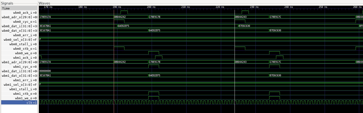
Waveform of PicoRV wordcopy from port 0 to port 1.
Using two fast Wishbone slaves, it takes 35 clock cycles to copy one word. Note that the actual word read and word write transactions only take 6 cycles. The rest, 29 cycles, is overhead. Bus utilization is at 17%. That’s not good.
With 4x unrolling in the assembly microcode, I can get to 24 clock cycles to copy one word, or 25% bus utilization. Better, but still nothing to brag about.
If I double the PicoRV’s clock speed, the amount of overhead would be cut in half and I would be able to achieve 46% bus utilization (6 clock cycles utilization, 7 clock cycles overhead).
Another option would be to add some logic to allow the PicoRV to kick off a short burst of read or write transactions, e.g. 4 words at a time. In that case, I would get 4x6 clock cycles utilization and 7 clock cycles overhead. That’s 77% bus utilization. I can live with that.
For slower slaves, bus utilization will increase further, because the slave response time starts to dominate. E.g. if it takes 10 clock cycles for a wishbone read or write transaction, we get 4x20 clock cycles utilization and 7 clock cycles overhead (assuming previous optimizations are implemented), or 92% bus utilization. Actual throughput would go down, however, because the slave is slow.
In the case of external memory, the slave is not slow, but latency is high. The best way to improve throughput for such slaves is through block transfers with multiple outstanding reads or writes. This requires additional logic on the bus master side, the bus slave side, and the bus fabric in between. I’m keeping this on my wishlist, as a stretch goal.
Praxos
Before I settled on the PicoRV-based DMA Controller, I integrated a Praxos-based DMA controller into BoxLambda. The design is essentially the same as shown in the PicoRV DMA block diagram but using a Praxos core instead of the PicoRV.
I did get it to work. The core and its unit test are located here: https://github.com/epsilon537/boxlambda/tree/picorv_dma/gw/components/praxos
The system test SoC and software are here:
- https://github.com/epsilon537/boxlambda/blob/picorv_dma/gw/projects/praxos_test/rtl/praxos_test_soc.sv
- https://github.com/epsilon537/boxlambda/blob/picorv_dma/sw/projects/praxos_test/main.c
The main reason I abandoned the Praxos approach is because I got frustrated with the limitations of the Praxos microcode. It took 250 lines of code to write a byte copy program, and it ran very slowly:
Possibly, I was going about it the wrong way. There may be a more elegant solution, but I didn’t see it, and I didn’t have much to go on. I certainly could have made it much better by adding a few instructions to the processor, e.g. a barrel shift, but I figured it would be better to invest in a core that already has a great ISA. Enter PicoRV.
Try It Out
Setup
- Install the Software Prerequisites.
- Get the BoxLambda repository:
git clone https://github.com/epsilon537/boxlambda/ cd boxlambda - Switch to the picorv_dma tag:
git checkout picorv_dma - Set up the repository. This initializes the git submodules used and creates the default build trees:
./boxlambda_setup.sh
PicoRV DMA CocoTB Unit Test
- Navigate to the picorv_dma component directory in the build tree and make the picorv_dma_test target to build all the PicoRV assembly programs the unit test depends on:
cd build/sim-a7-100/gw/components/picorv_dma make picorv_dma_test - Execute the CocoTB unit test program by running ctest in the current directory. You should see the following output:
ctest Test project /home/epsilon/work/boxlambda/build/sim-a7-100/gw/components/picorv_dma Start 1: picorv_dma_cocotb_test 1/1 Test #1: picorv_dma_cocotb_test ........... Passed 9.04 sec 100% tests passed, 0 tests failed out of 1 Total Test time (real) = 9.06 sec - If you find this a little underwhelming, you can run ctest again with the -V verbose flag to see more details.
PicoRV DMA System Test on Verilator
- Build the picorv_dma_sys_test project:
cd build/sim-a7-100/gw/projects/picorv_dma_sys_test make picorv_dma_sys_test_sim_sw - Execute the generated Verilator model. You should see the following output:
./Vmodel
...
Initializing SDRAM @0x40000000...
Switching SDRAM to software control.
Switching SDRAM to hardware control.
SDRAM init OK.
Load PicoRV WordCopy Program...
Taking PicoRV out of reset...
Internal memory wordcopy test
Configuring DMA request.
numElems = 32, srcAddr = 0x80e4, dstAddr = 0x8164
Kicking off DMA...
Waiting for completion...
Checking result...
PicoRV Wordcopy test successful.
External memory wordcopy test, port 0
Configuring DMA request.
numElems = 32, srcAddr = 0x40000000, dstAddr = 0x40000400
Kicking off DMA...
Waiting for completion...
Checking result...
PicoRV Wordcopy test successful.
External memory wordcopy test, port 1
Configuring DMA request.
numElems = 32, srcAddr = 0x50000000, dstAddr = 0x50000400
Kicking off DMA...
Waiting for completion...
Checking result...
PicoRV Wordcopy test successful.
External memory wordcopy to VRAM test
Configuring DMA request.
numElems = 32, srcAddr = 0x40000000, dstAddr = 0x10140000
Kicking off DMA...
Waiting for completion...
Checking result...
PicoRV Wordcopy test successful.
Putting PicoRV back into reset...
Load PicoRV ByteCopy Program...
Taking PicoRV out of reset...
Internal memory bytecopy test
Configuring DMA request.
numElems = 32, srcAddr = 0x81e5, dstAddr = 0x820b
Kicking off DMA...
Waiting for completion...
Checking result...
PicoRV Bytecopy test successful.
External memory bytecopy test, port 0.
Configuring DMA request.
numElems = 32, srcAddr = 0x40000001, dstAddr = 0x40000403
Kicking off DMA...
Waiting for completion...
Checking result...
PicoRV Bytecopy test successful.
External memory bytecopy test, port 1.
Configuring DMA request.
numElems = 32, srcAddr = 0x50000001, dstAddr = 0x50000403
Kicking off DMA...
Waiting for completion...
Checking result...
PicoRV Bytecopy test successful.
External memory bytecopy to VRAM test
Configuring DMA request.
numElems = 32, srcAddr = 0x40000001, dstAddr = 0x10140003
Kicking off DMA...
Waiting for completion...
Checking result...
PicoRV Bytecopy test successful.
PicoRV DMA tests successful.
Test passed.
PicoRV DMA System Test on Arty A7
- Connect a terminal program such as Putty or Teraterm to Arty’s USB serial port. Settings: 115200 8N1.
- Build the picorv_dma_sys_test project in an Arty A7 build tree (arty-a7-35 or arty-a7-100):
cd build/arty-a7-100/gw/projects/picorv_dma_sys_test make picorv_dma_sys_test_bit_sw - Download the generated bitstream file to the Arty A7:
make picorv_dma_sys_test_load - In the Putty terminal, you should see the same output as with the Verilator test build above.
Conclusion
A PicoRV-based DMA controller is very flexible. It can easily handle all the use cases I have in mind for BoxLambda, and then some. This flexibility comes at a price, however. The PicoRV32 DMA core as presented here is slow. A number of possible improvements have been identified, which I’ll tackle in the next post. Make it work first, then make it fast.