An attempt at a PicoRV32-based Soft DMA Controller - Optimizations.
Updated 2 April 2026: Corrected stale links.
Updated 16 November 2023: Added FPGA resource utilization.
Updated 23 December 2025: Removed reference to ‘On WSL’ documentation.
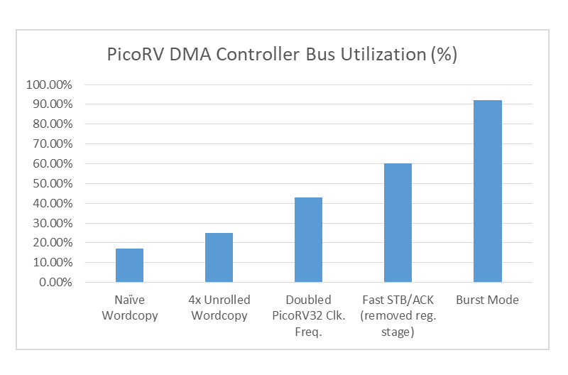
The PicoRV DMA Bus Utilization Improvements from Optimizations.
In my previous post, I introduced a PicoRV32-based, programmable DMA controller for BoxLambda. This DMA controller was very flexible, but also very slow. A loop-unrolled wordcopy program running on the PicoRV achieved only 25% bus utilization. Since then, I’ve been working on some performance optimizations. The DMA controller now achieves up to 92% bus utilization.
Recap
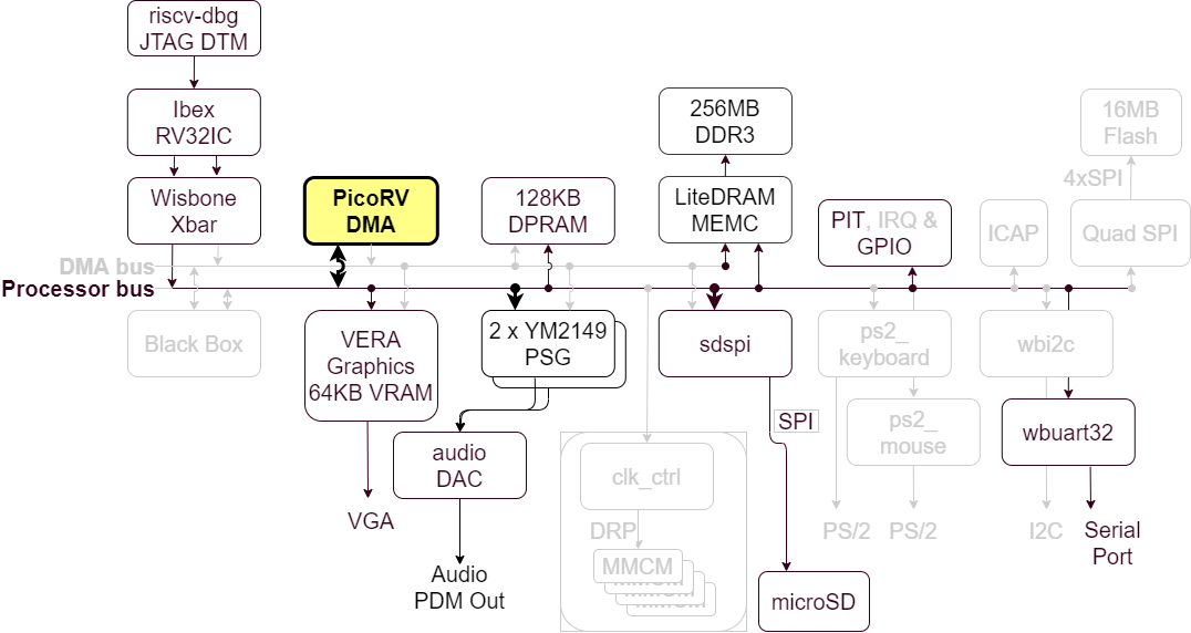
The PicoRV-based DMA Controller in the BoxLambda Architecture.
This is a summary of the current state of affairs for BoxLambda. We have:
- An Ibex RISC-V core, Wishbone shared bus, timer, two GPIO ports, UART core, and internal memory.
- DDR3 external memory access through the Litex Memory Controller.
- OpenOCD-based Debug Access, both on FPGA and Verilator.
- VERA-based VGA graphics: 2 layers tile or bitmap mode, 2 banks of 64 sprites, 128KB Video RAM, 256 color palette.
- Dual YM2149 PSG Audio.
- SD Card Controller and FatFs File System.
- A flexible but slow PicoRV32-based DMA Controller.
- A Picolibc-based standard C environment for software running on the Ibex RISC-V core.
- Test builds running on Arty-A7-35T, Arty-A7-100T, Verilator, and CocoTB.
- A Linux CMake and Bender-based Software and Gateware build system with support for automated testing and post-implementation memory updates.
Optimization 1: Doubling the PicoRV32 clock frequency
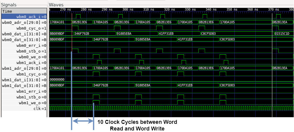
Waveform of PicoRV 4x unrolled wordcopy from port 0 to port 1, before doubling CPU clock frequency.
Looking at the bus transaction waveform of a wordcopy operation, it’s clear that the PicoRV is ‘losing’ a lot of time between transactions. Doubling the PicoRV’s clock frequency, i.e. running it at 100MHz, will cut this time in half. A clock frequency of 100MHz is still far below the PicoRV’s 250-450MHz Fmax on 7-Series Xilinx, so timing closure will not be a problem.
So far, all of BoxLamdba has been running in a single 50MHz clock domain, sys_clk. I introduced a new, 100MHz clock domain, sys_clkx2. Sys_clkx2 runs at exactly twice the rate of sys_clk so they stay in phase and I don’t have to insert CDC synchronization logic.
It was a straightforward change. The only issue was the LiteDRAM Memory Controller. LiteDRAM insists on owning the PLL primitive and generating the system clock. This approach allows LiteDRAM to generate additional clocks needed to implement the DDR PHY (When I wrote that all of BoxLamdba runs in a single 50MHz clock domain, that wasn’t entirely true. Parts of the memory controller are running at 100 and 200MHz). The downside of this approach is that to introduce an additional clock domain, I have to make a change in the LiteDRAM memory controller. LiteDRAM is code-generated, so I have to make the change in the master source code, the LiteX Migen/Python code base. It wasn’t a big deal, but I would have preferred to introduce the new clock domain in a separate Clock-and-Reset generator module.
Currently, I’m just running the PicoRV and its program memory in the new sys_clkx2 clock domain. I plan to switch over Ibex and possibly internal memory to the new clock domain as well. The rest of the system, including the Wishbone bus fabric will remain at 50MHz.

Waveform of PicoRV 4x unrolled wordcopy from port 0 to port 1, after doubling CPU clock frequency.
With the PicoRV running at 100MHz, 4x unrolled word copy bus utilization increased from 25% to 43%.
Optimization 2: Fast STB and Fast ACK - A tighter Wishbone Adapter

PicoRV32 Native to Wishbone Master Adapter.
PicoRV32 Native to Wishbone Master Transaction before optimization.
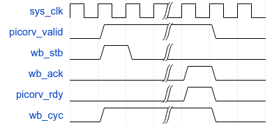
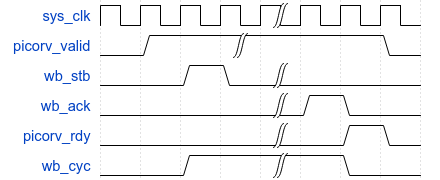
PicoRV32 Native to Wishbone Master Transaction after optimization.
The original PicoRV native-to-Wishbone adapter registered all signals. That means that when the PicoRV asserts its valid signal, the corresponding Wishbone STB signal gets asserted one system clock cycle later. This also happens in the return direction: when the Wishbone slave asserts ACK, the PicoRV ready signal is asserted one system clock cycle later. The PicoRV’s and the Wishbone slave’s outgoing signals are already registered. An additional register stage just to convert PicoRV-native to Wishbone signals is not needed. Combinatorial logic in combination with an FSM can be used to immediately turn a valid into an STB signal and an ACK into a ready signal without introducing a clock cycle latency in either direction.
With the Fast STB/ACK optimization in place, the 4x unrolled word copy bus utilization further increases from 43% to 60%.
PicoRV32 4x unrolled Word Copy with Fast STB/ACK and double PicoRV clock frequency.
Optimization 3: Burst Mode - A partial bypass
The next optimization is a bit more controversial (in my internal dialogue at least). In the most common DMA scenario, copying contiguous blocks of data, the data just passes unmodified through the PicoRV, which is a bottleneck. Instead, what we can do is, when the PicoRV issues a read transaction, have a little FSM module turn that into a burst of, say, 4 read transactions and store the result in a few Burst Registers. When the PicoRV issues a write transaction, the FSM can then write the contents of the burst registers to the address specified by the PicoRV. Additionally, this FSM can absorb a byte offset between source and destination, by storing the read words with a configurable byte offset in the Burst Registers. This way unaligned copies can be also handled efficiently.
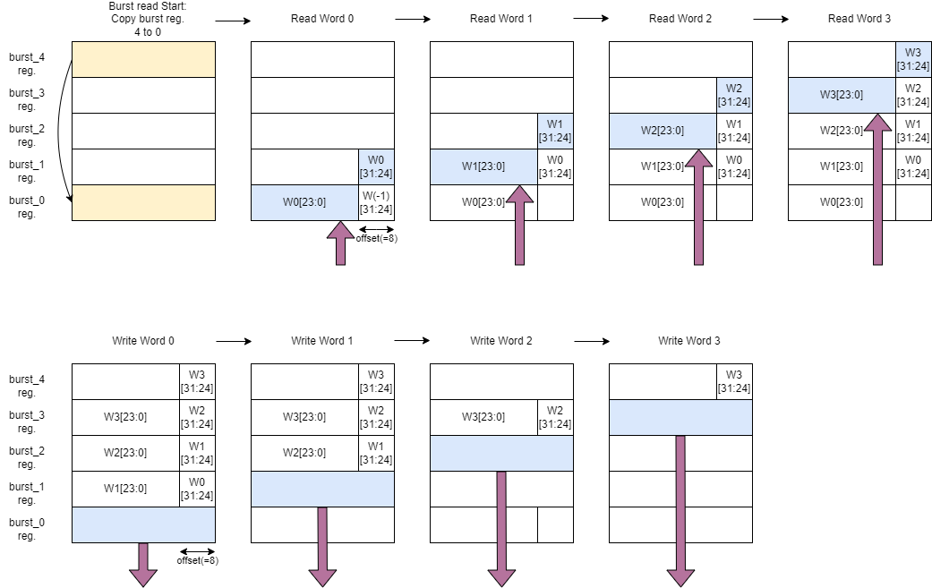
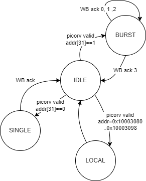
PicoRV DMA Burst Mode Sequence with 1-byte alignment offset. The top row shows a Burst Read and the bottom row a subsequent Burst Write.
In the diagram above, the top row shows a burst of four words being read and stored, with byte offset, in Burst Registers. The bottom row shows those four words being written out, from the burst registers to their destination. In this example, the destination-to-source byte offset is one byte.
A couple of things are worth noting:
- The burst read sequence and the burst write sequence are triggered by a PicoRV word read / word write request.
- These PicoRV word read / word write requests are Posted Reads and Posted Writes, i.e. the transaction completes immediately toward the PicoRV. The PicoRV does not stall until the entire burst is read or written. The PicoRV will only stall when a new read or write request is posted before a previous burst transaction has been completed. The posted burst transactions give the PicoRV copy-loop a few clock cycles of breathing room to do pointer arithmetic etc. without causing delays in the data path.

The PicoRV Instruction Sequence vs. Wishbone Transactions in Burst Mode.
- The address MSB is used to distinguish between Burst Mode transactions and regular transactions.
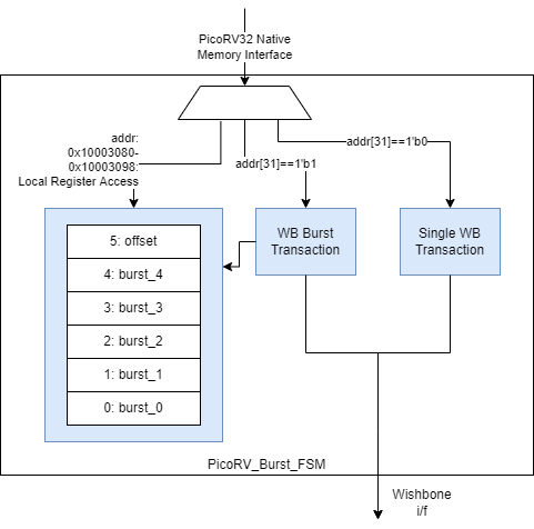
Block Diagram of the PicoRV Burst FSM Module.
The PicoRV Burst FSM Module’s FSM.
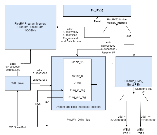
The PicoRV Burst FSM in the PicoRV DMA Core.
The Burst FSM module Verilog code can be found here: picorv_burst_fsm.sv.
A DMA wordcopy using Burst Mode results in 92% bus utilization.
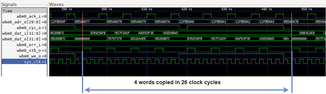
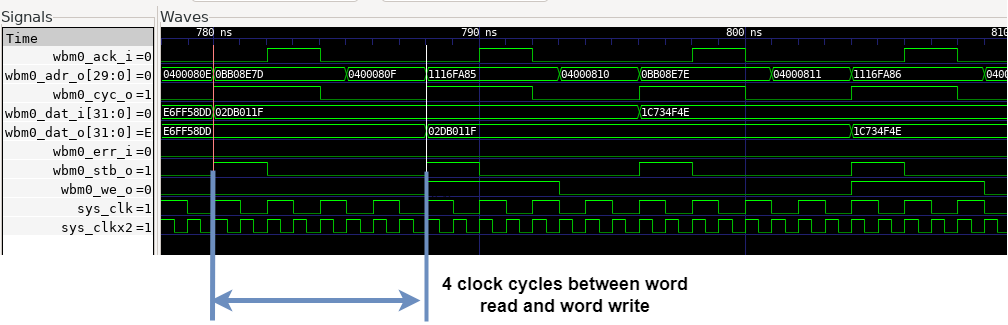
PicoRV32 Word Copy Using Burst Mode.
Utilization on Arty A7
Burst Mode comes at a price. This was the FPGA resource utilization of the PicoRV DMA core before adding Burst Mode:
| Slice LUTs | Slice Registers | Block RAM tiles | DSPs |
|---|---|---|---|
| 2088 | 1230 | 1 | 0 |
This is the current utilization:
| Slice LUTs | Slice Registers | Block RAM tiles | DSPs |
|---|---|---|---|
| 2522 | 1359 | 1 | 0 |
PicoRV Burst Mode Programs
Wordcopy_burst.picoasm is a PicoRV assembly program for doing word-aligned DMA copies, using Burst Mode. This is the core loop:
    ...
    or src, src, msb_set                 /*Set msb to engage burst mode*/
    or dst, dst, msb_set                 /*Set msb to engage burst mode*/
    or burst_end, burst_end, msb_set     /*Set msb to engage burst mode*/

burst_loop:
    /*Copy 4-word burst by 4-word burst*/
    lw tmp, 0(src)
    addi src, src, 16
    sw tmp, 0(dst)
    addi dst, dst, 16
    bltu src, burst_end, burst_loop
    ...
Bytecopy_burst.picoasm is a PicoRV assembly program implementing byte copy / unaligned word copy using Burst Mode. The core loop of the program is identical to the one shown above. However, it does require quite a bit of set-up code and wind-down code to handle all the alignment cases as well as transfer sizes that are not necessarily a multiple of 4 words.
Testing
picorv_burst_fsm_test.py is a CoCoTB test script testing the PicoRV Burst FSM module in isolation.
The original picorv_dma_test.py CoCoTB test script has been extended to include Burst Mode test cases.
Burst Mode introduced quite a bit of complexity. To test everything thoroughly, I added a system test, picorv_dma_sys_test_ext, consisting of multiple nested loops iterating over all permutations of a series of test vectors:
- Source Memory Type: Internal, External, VRAM.
- Destination Memory Type: Internal, External, VRAM.
- PicoRV Program: Byte Copy Single, Byte Copy Burst, Word Copy Single, Word Copy Burst.
- Source Pointer byte offset 0..3.
- Destination Pointer byte offset 0..3.
- Number of bytes/words to copy.
At the center of the nested loop is a parameterized DMA copy routine followed by checks verifying if the DMA copy is complete, without errors and out-of-bounds writes.
Other Changes
In the build system, I added CPP (C Preprocessor) as a preprocessor for .picoasm files. Being able to assign names to registers using #defines makes writing RISC-V assembly code a lot more manageable:
#define hir_base x1
#define burst_base x2
#define msb_set x3
#define mask_4_lsb x4
#define src x5
#define dst x6
#define num_elems x7
#define burst_end x8
#define single_end x9
#define stat_busy x10
#define tmp x11
...
_start:
    /*Set up constants.*/
    li hir_base, HIR_REGS_BASE_ADDR
    li burst_base, BURST_REGS_BASE_ADDR
    sw zero, BURST_OFFSET(burst_base)    /*no src-to-dest alignment offset.*/
    li msb_set, 0x80000000
    li mask_4_lsb, 0xfffffff0            /*mask to clear 4 lsbs*/
    li stat_busy, STAT_BUSY
wait_start:
    lw tmp, HIR3(hir_base)               /*HIR3: ctrl-status*/
    beqz tmp, wait_start
...
Try It Out
Setup
- Install the Software Prerequisites.
- Get the BoxLambda repository:
git clone https://github.com/epsilon537/boxlambda/ cd boxlambda - Switch to the picorv_dma_2 tag:
git checkout picorv_dma_2 - Set up the repository. This initializes the git submodules used and creates the default build trees:
./boxlambda_setup.sh
PicoRV Burst FSM CoCoTB Unit Test
Navigate to the picorv_dma component directory in the build tree and execute the picorv_burst_fsm_cocotb_test test case, using ctest:
cd build/sim-a7-100/gw/components/picorv_dma
ctest -V -R picorv_burst_fsm_cocotb_test
...<a lot of Wishbone transaction traces etc.>...
1/1 Test #2: picorv_burst_fsm_cocotb_test .....   Passed    1.80 sec
The following tests passed:
        picorv_burst_fsm_cocotb_test
100% tests passed, 0 tests failed out of 1
Total Test time (real) =   1.82 sec
PicoRV DMA CocoTB Unit Test
- Navigate to the picorv_dma component directory in the build tree and make the picorv_dma_test target to build all the PicoRV assembly programs the unit test depends on:
cd build/sim-a7-100/gw/components/picorv_dma make picorv_dma_test - Execute the picorv_dma_cocotb_test test case using ctest:
ctest -V -R picorv_dma_cocotb_test
...<a lot of Wishbone transaction traces etc.>...
1/1 Test #1: picorv_dma_cocotb_test ...........   Passed   25.67 sec
The following tests passed:
     picorv_dma_cocotb_test
100% tests passed, 0 tests failed out of 1
Total Test time (real) =  25.67 sec
PicoRV DMA Extended System Test on Verilator
- Build the picorv_dma_sys_test_ext project:
cd build/sim-a7-100/gw/projects/picorv_dma_sys_test_ext make picorv_dma_sys_test_ext_sim_sw - Execute the generated Verilator model. You should see the following output:
./Vmodel
...
Initializing SDRAM @0x40000000...
Switching SDRAM to software control.
Switching SDRAM to hardware control.
SDRAM init OK.
Load PicoRV Program WORDCOPY_BURST
Taking PicoRV out of reset...
Src Mem Type LOCAL, addr=0x84c4
Dst Mem Type LOCAL, addr=0x83c4
Dst Mem Type EXT_MEM_1, addr=0x50000100
Dst Mem Type LOCAL, addr=0x83c4
...
Load PicoRV Program BYTECOPY_BURST
Taking PicoRV out of reset...
Src Mem Type LOCAL, addr=0x84c4
Dst Mem Type LOCAL, addr=0x83c4
Dst Mem Type EXT_MEM_1, addr=0x50000100
...
Putting PicoRV back into reset...
All tests passed.
Test passed.
PicoRV DMA Extended System Test on Arty A7
- Connect a terminal program such as Putty or Teraterm to Arty’s USB serial port. Settings: 115200 8N1.
- Build the project in an Arty A7 build tree (arty-a7-35 or arty-a7-100):
cd build/arty-a7-100/gw/projects/picorv_dma_sys_test_ext make picorv_dma_sys_test_ext_bit_sw - Download the generated bitstream file to the Arty A7:
make picorv_dma_sys_test_ext_load - In the Putty terminal, you should see the same output as with the Verilator test build above.
Conclusion
Optimization is a dangerous game. Before you know it, your initial clear and simple design is polluted with complexity and hacks. Doubling the CPU clock and the fast STB/ACK optimization are nice improvements, but Burst Mode falls into the dangerous optimization category. Burst Mode is fast, but it’s also hacky and it introduces quite a bit of complexity. I’m going to leave it in because it opens the door to implementing multiple outstanding reads and writes, but I have taken this DMA chapter far enough for the time being. There is much more to do. The next topic is a (USB?) keyboard and mouse for BoxLambda.
Interesting Links
WaveDrom is an excellent tool for creating timing diagrams.